You must be signed in to read the rest of this article.
Registration on CDEWorld is free. Sign up today!
Forgot your password? Click Here!
There are three general steps to the digital restoration workflow: 1) digital recording or scanning of the tooth geometry to capture digital data; 2) manipulation of the digital data with a software program to create the volume model of the restoration; and 3) production technology that translates the volume model into the restoration.1 Early systems were easily divided between dental office systems and dental laboratory systems as all three steps were completed in the same location. However, newer digital impressions systems, such as iTero™ (Cadent™, www.cadentinc.com) and the Lava™ Chairside Oral Scanner C.O.S. (3M™ ESPE™, www.3mespe.com), are able to record digital data chairside and electronically transmit it to the dental laboratory. The CEREC® Acquisition Center (AC) (Sirona Dental, www.sirona.com) and E4D Dentist™ (D4D Technologies, www.e4dsky.com) were both introduced as digital systems capable of imaging, designing, and fabricating ceramic restorations chairside.2,3 Sirona Dental has introduced the CEREC Connect software program that enables the CEREC AC camera to record digital impressions for electronic transfer to a dental laboratory.4,5 In late 2010, D4D Technologies has plans to link its chairside digital impression system to dental laboratories and other recipients through its proprietary E4D Sky™ Network.2
The dental laboratory has two complementary applications for using the transmitted digital impression data. The laboratory technician can directly input the digital data into a compatible CAD/CAM program to design and mill substructures or full-contour restorations. This poses a critical decision for the dental laboratory. Early adopters were limited to “closed architecture” systems in which the digital data could be used only with matched software and hardware from the manufacturer of the intraoral scanner.6 Today, a more “open architecture” is evolving as manufacturers enter into partnerships with third-party software and hardware companies to use their digital scan data. The laboratory technician can also use the digital impression data to process working models. The data is transmitted to a digital manufacturing center for post-processing of the images and creates the models via a subtractive CAD/CAM milling process (iTero) or an additive resin printing process known as stereolithography (Lava C.O.S., CEREC).7 Once the models are delivered to the dental laboratory, the CAD/CAM restoration is completed and returned to the dental office for delivery to the patient, completing the digital workflow.
The investment of time and effort to learn a new treatment workflow is a key element when considering the integration of a new process or technique in the dental office. There are several concepts to consider for the integration of any digital impression system.
Digital Impression Concepts
Tooth preparations for CAD/CAM ceramic restorations must take into account the features required for all-ceramic restorations as well as unique features required for milled restorations.8,9 CAD/CAM restorations are optimally milled when the tooth preparation has a smooth, flowing surface with no sharp angles. Complex preparation geometry—including sharp internal angles, parallel walls, and acute curves—are more difficult to image and mill accurately. Doctors with a strong background in cast restorations will have to make a concerted effort to alter their usual tooth preparations to produce successful milled ceramic restorations. Rounded internal angles, smooth margins, and flowing curves facilitate the accuracy of the imaging and milling process. Geometry of the margin design, such as a shoulder or chamfer, is not a critical factor in recording the tooth preparation. As long as the margin is visible, the scanner can record it.
An obvious consideration is the selection of an intraoral scanner to record the digital impression. There are differences in the technology used in the digital cameras as well as the process for recording images and creating the digital models.
The E4D Dentist IntraOral Digitizer uses red laser light and micro-mirrors oscillating at 6,000 and 20,000 cycles per second to capture digital images of teeth and soft tissues, stone models, or impressions.10 It has a relatively short vertical profile (8 mm), so the patient is not required to open particularly wide for posterior images.11 The IntraOral Digitizer is positioned directly over the prepared tooth to initiate the scanning process. The optimum focal distance is achieved by using an autoclavable rubber stop (“stand-off”) on the face of the scanner to stabilize it on the adjacent teeth. In those instances when scanning parallel to the enamel rods or through thin translucent sections of enamel, a reflective liquid (E4D Accent) is needed to capture the data. For a true 3-D capture, typically nine separate images are required to record all of the exposed surfaces of the prepared and adjacent teeth in the quadrant. An ICE™ (I C Everything) feature of the software takes photographic images of the teeth and gingival tissue. As successive images are recorded, they are wrapped around the developing 3-D model to create the ICE view. This provides the user with unrestricted images of the actual hard and soft tissue and aids with margin identification.11
CEREC AC has a blue light-emitting diode (LED) camera rather than the red laser light camera of prior CEREC systems. The shorter-wavelength blue light projected by the LED allows for greater precision of the resultant optical image.12 The camera uses an “active triangulation technique” to record images. A pattern of blue light is projected onto the object and then read back at a slightly different angle. It uses a telecentric beam, which permits the capture of essential information from all of the prepared tooth’s surfaces in a single view. The camera is positioned directly over the prepared tooth to initiate a scan. Once the camera is stabilized within the 14-mm focal distance and held motionless by contact with adjacent teeth, the camera will automatically record an image.13 This prevents the recording of inaccurate images due to camera movement. Once the image is recorded, the camera is moved over adjacent teeth to record additional images. The software stitches the overlapping data from the successive images to calculate a single 3-D model.
The iTero intraoral scanner is the largest of those in the market and does require additional intraoral space compared to other scanners for digital impressions. The scanner uses parallel confocal imaging to capture a 3-D digital impression.10,14 The scanner emits a beam of laser light through a small hole and directs it toward the tooth surface. Only an object at the proper focal length will reflect light back through the filtering device.15 The scanner captures 100,000 points of laser light and has accurate focus at more than 300 focal depths.11 The focal depth images are spaced approximately 50 μm apart. The camera covers a 14 mm2 x 18 mm2 area at a scan depth of 13.5 mm.15 No reflective medium is required for the laser light to be reflected from intraoral surfaces. It does not have to be held a fixed distance from the tooth and will scan when touching the teeth.10 A foot pedal is used to activate the scanner to capture successive images. After each scan, the option to accept or reject the scan is presented to the clinician. Once accepted, the scan is integrated into the digital model. The unit also provides visual and verbal prompts for active guidance during the digital impression process.14 The software will prompt for a series of five scans (occlusal, facial, lingual, mesio-proximal, and disto-proximal views) per prepared tooth, with additional scans required for the adjacent teeth and opposing dentition. The usual series may range from 15 to 30 scanned images to record the preparation, opposing teeth, and the occlusal relationship.15
The Lava C.O.S. intraoral scanner is 13.2 mm wide at the working end and contains 192 LED and 22 lens systems. The Lava C.O.S. intraoral scanner is based on the principle of active (optical) wavefront sampling.16 Active wavefront sampling refers to imaging 3-D information from a single-lens imaging system. Three sensors capture the clinical view from different perspectives and generate 3-D surface areas in real time by means of proprietary image-processing algorithms.16 This “3-D-in-motion” technology records continuous 3-D video images to create a volume model of the quadrant or arch in real-time on the computer monitor. The camera captures 20 3-D data sets per second, or about 2,400 3-D data sets, or 24 million data points per arch, to create the volume model.16,17 Lava C.O.S. is the only intraoral video scanner as opposed to the still image mode of other systems. The camera is held from 5 mm to 15 mm from the surface of the teeth and soft tissues to activate scanning.10 Movement of the camera outside this focal range stops the video recording until the camera is brought back within the range. This serves as a fail-safe mechanism to avoid recording poor data. The amount of the dentition to be recorded is determined by the dentist and can include a sextant to a full arch.18
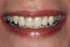
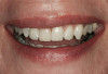
A key element in creating an accurately fitting restoration is precisely reproducing the geometric shape of the tooth preparation.19 Traditionally, this has been done with a final impression using polyvinylsiloxane or polyether materials. Digital impressions rely on a similar need for accuracy. As much as dentists may prefer it, no marketed system has the capability to image the tooth surface through soft tissues. Soft tissues must be retracted from the margins of the tooth preparation to ensure direct visual access for the scanner. Any clinical technique useful for retracting soft tissues when making a traditional impression will be useful for recording digital impressions. As long as the margin is visible on the monitor, it can be recorded and identified. Many clinicians find the use of electrosurgery or soft tissue lasers very helpful in easily creating lateral space for recording images, but retraction cord and pastes are commonly used as well (Figure 1).
Liquid contaminants such as blood and saliva interfere with accurate traditional impressions. Similarly, they also interfere with digital impressions. Fluids must be isolated from the field of view of the camera. The tongue and cheeks must also be controlled from interfering when making an impression. This is true for both traditional and digital impressions. For an analog impression, the tongue and cheeks are controlled for the length of time required for injection of the light-body impression material and placement of the tray and impression material. For a digital impression, they need only be controlled for the shorter time required to image the desired area.
Intraoral access for the camera is an obvious concern about moving to digital impressions. In every dental practice, there is a group of patients with either limited space available in the posterior of the mouth or who have a strong gag reflex that proves problematic for placement of an impression tray. An initial glance at an intraoral digital scanner may lead one to think that it may be more restrictive in its use compared to an impression tray. However, the working tip of most scanners is actually comparable in size to other common intraoral devices such as electric handpieces and curing lights. The use of an intraoral scanner may also be an advantage with a patient who gags because it does not touch the soft palate, it is used for a shorter period of time, and the patient can have a break between images if needed.
A unique feature of a digital impression system is the immediate feedback afforded to the clinician. Once the digital impression has been recorded, the tooth preparation can be viewed from various perspectives and at substantial magnification on a computer monitor. If discrepancies in the preparation or digital image are noted, they can be corrected immediately and the case quickly rescanned. This should minimize, if not prevent, case remakes due to inaccurate impressions because problems can be identified while the patient is still in the office. Laboratories can make a well-fitting restoration on accurate impressions, and the ability to critically assess the scanned preparation immediately cannot help but to improve the accuracy of the data transmitted to the laboratory for processing.
A number of the considerations of moving to digital impressions are not unique to a particular system. To better illustrate some of the specifics involved with digital impressions, a case using the Lava C.O.S. system will be presented.
Digital Workflow
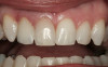
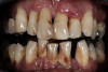
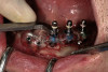
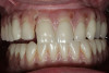
A patient presented with large amalgam restorations and recurrent caries on teeth Nos. 2 and 3 (Figure 2). After reviewing the treatment options, the patient chose all-ceramic crowns to restore the teeth. The specific all-ceramic crowns selected for the case were zirconia crowns. After completion of the crown preparations, soft-tissue retraction was achieved and the tooth surfaces were cleaned and dried (Figure 3). The teeth and soft tissues were isolated and lightly sprayed with a titanium-dioxide powder to create a reflective surface (). The powder provides contrast points for scanning to enhance recording the 3-D models and to improve the speed of recording.
After the preparation has been accurately recorded, additional teeth in the quadrant or arch are scanned to complete the desired model (Figure 5). It is not necessary to complete the entire scanning process in a single pass of the camera. Overlapping segments of the arch or quadrant may be scanned and the segments assembled into a single volume model. This process is referred to as “strip scanning.” After each section is scanned, it is superimposed over the previous scan, and the option is presented to accept or delete the newest scan. The latest scan can be deleted without affecting the previous scan. Once it has been accepted, it is assimilated into the previous scan and added to the volume model. Once assimilated into the model, it cannot be deleted. The entire model must be deleted and the model rescanned. The touch-screen monitor allows the digital model to be rotated, magnified, and evaluated through 3-D stereographic review to assess accurate recording of the dentition.17
To record the relationship of the opposing digital models, the patient is closed into maximum intercuspation (MI) and asked to hold the position. The cheek is retracted and the occlusion is recorded by scanning the facial surfaces of the maxillary and mandibular teeth and adjacent soft tissues. This scan relates the opposing arches or quadrant scans by aligning them with the data in the buccal scan (Figure 6). No bite registration materials are required. No digital system currently has the capability of predictably recording functional lateral guidance. Three separate scans can be recorded for the buccal scan: right posterior, left posterior, and anterior. One or all three scan areas may be used to align the opposing models for the case if quadrant or full-arch models are recorded.
A common question about digital scanning of the dentition relates to the length of time required. The maximum time allowed to scan a maxillary or mandibular model with the Lava C.O.S. unit is 7 minutes. Because the quadrant or full arch is scanned in strips or segments, this is more than sufficient time to record the dentition. Quadrants are usually scanned in 2 to 3 minutes and buccal registrations in less than 1 minute. Two to three teeth is the minimum acceptable amount of data required to create a model. Similarly, there is a minimum amount of data required for the buccal scan to accurately record the occlusal relationship of the opposing models. If insufficient buccal scan data is recorded, the software will not relate the opposing models and the operator will be prompted to remake the buccal scan.
After the digital models have been recorded, the prepared tooth is identified on the digital model before submitting the case electronically to the laboratory. In most cases, the laboratory technician will identify the margin of the preparation once the data has been downloaded to the laboratory. However, the dentist also has the option to mark the margin of the preparation before uploading the case. This facilitates communication with the laboratory technician for an accurate result.
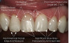
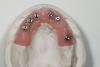
After the dentist has approved the recorded scans, the electronic laboratory prescription is completed on the Lava C.O.S. unit, and the case is digitally transmitted to the dental laboratory. The laboratory is notified through their Case Manager program that a new case is ready to be downloaded for processing. The laboratory technician downloads the file and opens it within the Margin Marking program. The first step is to select either a full-arch or quadrant articulator for the case so that the models may be correctly aligned on the articulator (Figure 7). The second step is to select the locations to section the models to facilitate removable dies. Finally, the technician will mark the margins of the prepared teeth (Figure 8). Several different screen views are available to aid in margin marking. There is an occlusal view window in the path of insertion of the preparation as well as a sagittal view window. There is also a series of magnified images selected from the scanned model that can be reviewed as the margin is identified 360° on the model. There is also an option to use 3-D glasses to view the margins in 3-D on the computer monitor.
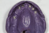
After the laboratory technician has completed the margin marking process, the data file is electronically transmitted to 3M ESPE for fabrication of the working models. The quadrant or full-arch models are made using stereolithography (SLA). Stereolithography is a rapid prototyping technology that uses a laser micro-curing process that creates the models from a volumetrically stable polymer resin material.20 The resin models are positioned within the selected articulator with a friction-lock system allowing for removal of the models from the articulator (Figure 9). Additional SLA models may also be requested, such as a solid model of the tooth preparation and adjacent teeth as well as a soft-tissue model, as verification models for the laboratory.
Design and Fabrication
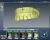
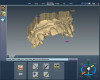
One of the advantages of the digital workflow is that while the SLA resin models are being fabricated, the dental laboratory can input the digital impression data directly into the Lava Design 5.2 CAD/CAM software program for design and fabrication of the restoration (Figure 10). The Lava all-ceramic crown system, consisting of a CAD/CAM fabricated zirconia substructure that is veneered by a laboratory technician with a layering porcelain, was introduced in 2000.21,22 A new total CAD/CAM Lava all-ceramic crown has been introduced with a Digital Veneering System (DVS). The Lava™ DVS full contour crown consists of a CAD/CAM designed and milled zirconia substructure with a corresponding CAD/CAM designed and milled veneer layer or “topper” that is subsequently fused to the zirconia substructure. A key element in the long-term success of a veneered crown is adequate support of the veneering layer by the substructure. Early CAD/CAM design programs were limited in the ability to customize the shape of the substructure, resulting in overly thick veneer layers that could lead to chipping or fracture. The Lava Design 5.2 program begins the design of the substructure and digital veneer by proposing an anatomically correct, full-contour crown (Figure 11). The program automatically reduces the full-contour design to provide optimal anatomic support for the veneering layer as well as the appropriate thickness and unique contour of the zirconia substructure for the prescribed restoration (Figure 12). It also proposes the digital veneer that can be customized to the unique contours and occlusal contacts of the case (Figure 13). The substructure is milled from Lava zirconia that can be colored based on the desired shade of the crown. The digital veneer is milled from glass ceramic blocks that are available in four shades (Figure 14).
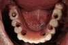
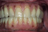
The milled and sintered zirconia substructure is fit to the SLA die model. The external surface of the zirconia substructure is air-abraded using Rocatec™ Soft (3M ESPE) to prepare it for fusion to the digital veneer. The digital veneer is carefully cut from the block holder and placed in distilled water for 1 minute to allow water to uniformly penetrate into the glass ceramic. The Lava DVS Fusion Porcelain is mixed in one of the 10 shades appropriate for the shade of the restoration and painted on the internal surface of the digital veneer. Additional fusion porcelain is placed on the external surface of the zirconia substructure, and the digital veneer is positioned over it. The excess fusion porcelain is expressed from between the two layers as the digital veneer is compressed to place over the substructure (Figure 15). The excess fusion porcelain is smoothed out at the margins, then fired in a porcelain oven. The final contours of the restoration are refined on the articulated SLA models. The final shade of the crown is influenced by the shade of the colored zirconia substructure, fusion porcelain, and the digital veneer. The fused crown can also be customized with surface stains and glazes (Figure 16). The case is returned to the dental office for delivery to the patient with a choice of adhesive or conventional cementation (Figure 17 and Figure 18).
Conclusion
Digital systems with CAD/CAM technology are continuing to develop efficient, predictable workflows for restorative dentistry. The immediate feedback on the scanned preparation ensures the transmission of consistently accurate information to the dental laboratory. The CAD/CAM process offers new and innovative materials and techniques for restoration fabrication.
ACKNOWLEDGMENT
The author would like to acknowledge Mary Valentine, CDT, of Innovative Dental Laboratory, for fabrication of the crowns in this case.
Disclosure:
The author has received clinical research support from 3M ESPE and Sirona.
References
1. Beuer F, Schweiger J, Edelhoff D. Digital dentistry: an overview of recent developments for CAD/CAM generated restorations. Br Dent J. 2008;204(9):505-511.
2. Levine N. To the sky and beyond. Dental Products Report. 2009; Oct:116.
3. Moermann WH. The evolution of the CEREC system. J Am Dent Assoc. 2006;137 Suppl:7S-13S.
4. Fasbinder DJ. Innovations in CAD/CAM technology: CEREC AC with Bluecam. Oral Health. 2009;Mar:22-31.
5. Touchstone A, Nieting T, Ulmer N. Digital transition: the collaboration between doctor and technician in CAD/CAM restorations. J Am Dent Assoc. 2010;141(2 Suppl):15S-19S.
6. Tinschert J, Natt G, Hassenpflug S, et al. Status of current CAD/CAM technology in dental medicine. Int J Comput Dent. 2004;7(1):25-45.
7. Schoenbaum TR. Decoding CAD/CAM and digital impression units. Dent Today. 2010;29(2):140-145.
8. Tsotsos S. A historical perspective of tooth preparation for CEREC technology. Oral Health. 2009;Mar:55-60.
9. Severance G, Swann L. The Take Care approach to treatment planning, preparation and design for CAD/CAM restorations. Oral Health. 2009;Mar:47-52.
10. Kachalia PR, Geissberger MJ. Dentistry a la carte: in-office CAD/CAM technology. J Calif Dent Assoc. 2010;38(5):323-330.
11. Birnbaum NS, Aaronson HB. Dental impressions using 3D digital scanners: virtual becomes reality. Compend Contin Educ Dent. 2008;29(8):494-505.
12. Mehl A, Ender A, Moermann W, et al. Accuracy testing of a new intraoral 3D camera. Int J Comput Dent. 2009;12(1):11-28.
13. Pieper R. Digital impressions—easier than ever. Int J Comput Dent. 2009;12(1):47-52.
14. Garg AK. Cadent iTero’s digital system for dental impressions: the end of trays and putty? Dent Implantol Update. 2008;19(1):1-4.
15. Henkel GL. A comparison of fixed prostheses generated from conventional versus digitally scanned dental impressions. Compend Contin Educ Dent. 2007;28(8):422-431.
16. Syrek A, Reich G, Ranftl D, et al. Clinical evaluation of all-ceramic crowns fabricated from intraoral digital impressions based on the principle of active wavefront sampling. J Dent. 2010;38(7):553-559.
17. McMaster, D, Cohen, B, Spitz, SD. Digital workflow. Dental Economics. 2008;Aug:30-36.
18. 3M ESPE. Lava Chairside Oral Scanner C.O.S. Technical Datasheet; 2009.
19. Alhouri N, McCord JF, Smith PW. The quality of dental casts used in crown and bridgework. Br Dent J. 2004;197(5):261-264.
20. Dunne P. Digital dentistry and SLA technology. Lab Management Today. 2008;Nov/Dec:44-45.
21. Suttor D, Bunke K, Hoescheler S, et al. LAVA—the system for all-ceramic ZrO2 crowns and bridge frameworks. Int J Comput Dent. 2001;4(3):195-206.
22. Suttor D. Lava zirconia crowns and bridges. Int J Comput Dent. 2004;7(1):67-76.