

Managing Curved Canals: the Straight-Away and Super Glide Path Technique
Melvyn Segal
Unfortunately, not all root canals are straight. Clinicians regularly encounter curves of different degrees and in various places all along the root canal system. These curves cause a host of problems, including ledge formation, perforation, apical transportation, zip formation, and file separation (Figure 1).1 This article is intended to aid the clinician in identifying the degree, type, location, and direction of the various root canal curves and will provide suggestions for their management and instrumentation. The technique advocated by the author and presented in this article entails understanding how to use and exploit rotaries, and will even benefit the practitioner who only undertakes the management of straight canals. A system offering a .02 tapered file (such as K3, Quality Endodontic Distributors, Peterborough, England; RaCe, FKG Dentaire SA, La Chaux-de-Fonds, Switzerland; or Quantec™, SybronEndo, Orange, CA) is integral to the technique.
The discussion assumes that throughout the root canal procedure, proper irrigation, lubrication, and recapitulation occurs and that there is no violation of the apical termination, and therefore those aspects will not be discussed in detail.
CLINICAL TECHNIQUE Apical Curves
The first step is to gain access to the pulp, and then, using a tapered diamond, flare the walls of the pulp chamber to such an extent that all of the canal orifices in the chamber will be visible with one eye closed, as if looking into a camera lens.2 This is called “straight-line access” (Figure 2). Straight-line access eliminates the irregular walls in the pulp chamber, allowing the file to negotiate the canal with less stress. When straight-line access is achieved, the file will not have to bend to get into the root canal orifice.
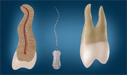
After gaining straight-line access, a No. 8 or a No. 10 reamer—not a K file—should be used to go to working length. This step will serve four purposes: to check the patency; to determine the working length; to achieve the initial glide path; and to make an impression of the canal. The advantage of using a reamer over a K file is that the reamer’s “dead soft” quality yields a perfect impression of the curves in the canal when it is removed (Figure 3).3 Before removing the reamer, however, use a magic marker to mark the labial or buccal surface handle of the instrument to serve as a reference point. The reamer’s impression mirrors the degree, type, location, and direction of the curve. Because the reamer is more flexible than the K file, there is also less chance of apical transportation or zipping. Avoid using either a stainless-steel hand file or a stainless-steel reamer above No. 10 in a curved canal because they are too inflexible.
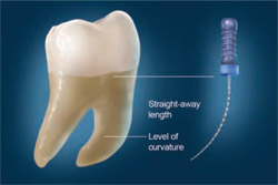
If the impression shows that the curved canal is at the apical third, as shown in Figure 4, measure the reamer up to the curve. Use this straight-away length to instrument with orifice openers, such as the K3 shapers, in a crown-down fashion, up to the curve but not beyond. Where the shapers cannot reach the total straight-away length, continue instrumenting with .04 rotary nickel titanium (Ni-Ti) instruments in a crown-down fashion until the total straight-away length is negotiated (ie, up to the curve). At this point, going beyond the curve with inflexible orifice openers and .04 rotary Ni-Ti instruments may perforate or ledge the canal. Making this “straight-away” will remove all of the restrictive dentin in the coronal and middle two thirds of the canal, which will facilitate subsequent files in reaching working length.4
After achieving patency, making an impression, creating an initial glide path, and crafting the straight-away, the next step is to create a well-defined glide path, or what the author calls a “super” glide path. This will make it easier to negotiate the canal and curve with subsequent instruments. To create a super glide path, .02 tapered rotary Ni-Ti instruments should be used in a crown-up fashion; that is, first use a .02 No. 15 to working length; then use a .02 No. 20 to working length; and, if possible, finish with a .02 No. 25 to working length. Because a straight-away was created, there should be no problem negotiating the curve to working length using .02 tapered rotary Ni-Ti files. These highly flexible .02 rotaries will glide right through the canal and past the curve.
Now that this super glide path has been created with the .02 tapers, the .04 tapered Ni-Ti rotary instruments can be used in a crown-down fashion beyond the curve to working length; ie, use a .04 No. 35 followed by a .04 No. 30, and so on, finishing with a .04 No. 15. Recapitulate until the master apical file reaches working length, which in a severely curved canal should be a No. 20 or No.25. If the .04 tapers will not advance easily, use .02 tapers in a crown-down fashion and then return to the .04 tapers. Avoid using .06 rotary Ni-Ti tapers in a canal with a sharp curve as these wider tapers have less flexibility, increasing the chance of file separation.
Banana Curves
By contrast, if the impression shows a mid-root banana curve, obtain the straight-away length by measuring up to the level of curvature (Figure 5).4 Again, use the impression of the canal for these calculations. Because mid-root banana curves tend to be more gradual and less acute than apical curves, they allow for straight-away measurement all the way to the level of curvature. This is unlike the straight-away in the acute apical curve, which stops at the very beginning of the curve. The short straight-away distance in the mid-root banana curve requires only shapers to negotiate the straight-away length, unlike the apical curve, whose length may require both shapers and rotary Ni-Ti instruments. Because the straight-away length in mid-root banana curves is mostly located in the coronal third of the root, which is wide, it is thus able to accommodate shapers. Do not attempt to go around the bend with shaper instruments or any orifice openers because this may create a ledge or perforation. The straight-away in this case transforms a C-shaped canal into a J-shaped canal (Figure 6).5 Always direct the shapers away from the furca so as not to strip or perforate the thin wall in that location. After making a straight-away, create a super glide path by following the steps described above, then crown-down with .04 rotary Ni-Ti instruments, which will now easily glide past the mid-root curve.
S-Shaped Curves
Now the attention shifts to the challenging S-shaped curve, usually found in upper premolars (Figure 7). Because S-shaped curves consist of two curves, they usually present a greater risk of file separation than the apical and mid-root banana curves, as the file must pass through both curves.3 Make a straight-away up to the beginning of the first curve. This length is usually short enough for the shapers or any orifice openers alone to make the straight-away. Look at the impression to calculate the measurement, then create a super glide path to working length by using .02 rotary Ni-Ti instruments in a crown-up fashion as described above (.02 No. 15; .02 No. 20; and .02 No. 25). Then use these same .02 tapers, this time in a crown-down fashion, from .02 No. 35 to .02 No. 15. Recapitulate until at least the master apical file reaches to working length, then start to crown-down with .04 rotary Ni-Ti instruments. This technique, though requiring a greater number of files than the apical or mid-root banana curves, is safer because it helps prevent file separation. It would be unwise to crown-down initially with .04 rotary Ni-Ti instruments because the S-shaped curve requires negotiating two curves.
Merged Canals
Where a root has two canals that merge into one near the apex, attack one of the curves head on and outflank the other. This type of curve is usually found in the mesial roots of lower first and second molars (Figure 8). Here again, achieve patency, make an initial glide path, and make an impression all in one step by using a No. 8 or a No. 10 reamer to working length in the straighter of the two canals. Then create a straight-away, make a super glide path, and crown-down to working length in the straighter of the two canals only. In the second canal, crown-down only to the merger point; do not attempt to deflect the file around the turn because it may bind and separate.6
DISCUSSION
Many clinicians instrument the curve in the canal exclusively by hand and only use rotaries for the straight part of the canal. There are also some clinicians who use hand instruments greater than a No. 10 to make a glide path. Neither of these approaches is advisable because hand instruments greater than No. 10 in the canal may cause an iatrogenic event. Even if a No. 15 hand file passes through a severely curved canal initially, very often it will not be able to negotiate the curve a second time. The only hand instrument that should be used in a severely curved canal is a No. 8 or a No. 10 reamer, which will follow the curve without any need to pre-bend. The author has found through experimenting on extracted teeth with curved canals that hand instruments above No. 10 can easily create a ledge or transport or zip the apex. Often, a zip or transportation may not even be apparent on a radiograph. The clinician will believe that he or she performed the perfect root canal on a curved root, when in reality the canal was transported or zipped.
When preparing a straight canal, any system will work. But when it comes to a severely curved canal, the curve has to be well-prepared before using any of the systems to prevent an iatrogenic event. Just like a tooth with a severe curve must be loosened with either proximators, luxators, elevators, or periotomes before the extraction forceps are employed so that the root does not fracture during the extraction process, so too a well-defined glide path must be made to prepare the curved canal for instrumentation and shaping.
ACKNOWLEDGMENTS
The author would like to acknowledge Michael Reiss, Yitzchok Segal, and Dr. Shahab Cohen for their assistance in the preparation of this article.
REFERENCES
1. Ingle JI. Root canal preparation. In: PDQ Endodontics. BC Decker, Hamilton, Ontario: 2005;129.
2. Brave D, Koch K. Locating the elusive root canal. DentalTown. 2007;8(1):53.
3. Curtis ML. 100’s of Pearls on Endodontics. Chapter 5: Tips and Tricks for Common Endo. Hundreds of Pearls, LLC; Michael L. Curtis, Publisher. 2005;93-95.
4. Mounce R. Negotiating challenging mid root curvatures: rounding the bend. Dentistry Today. 2007;26(2):108.
5. Deutsch AS, Musikant BL. Innovations in endodontics: the same ends by simpler means. Endo Tribune U.S. Edition.
6. Weathers A. File breakage in endo. LVI Visions. 2005;Sept/Oct/Nov:44.
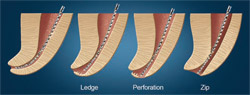 | 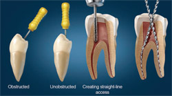 |
| Figure 1 Latrogenic events. | Figure 2 Straight-line access. |
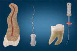 | 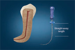 |
| Figure 3 Making an impression. | Figure 4 Obtaining a straight-away length. |
 | 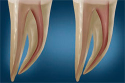 |
| Figure 5 Level of curvature. | Figure 6 Turning a C-shaped canal into a J-shaped canal. |
 | 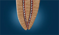 |
| Figure 7 An S-shaped curve. | Figure 8 Merging canals. |
| About the Author | |
 | Melvyn Segal, DDS Associate Clinical Professor New York University College of Dentistry New York, New York Private Practice Brooklyn, New York |

