

The Use of Narrow-Bodied Implants in Limited Bone and Restricted Spaces
Tommaso Ravasini, DMD
Our multi-generational familiarity with narrow-bodied solid implants dates back to the period when implant restorative procedures extended over very lengthy periods, frequently beyond the endurance of many patients. The patients’ discontent with the lengthy procedures manifested itself when patients regretted the experience of having accepted implants as a cure-all and would not recommend this solution to their friends or relatives. The reason for disappointments was the lengthy in-treatment procedure that was needed for the osseointegration of the definitive implant fixture. This was further aggravated as the patient’s only interim remedy was to wear removable dentures or to be without teeth throughout the treatment. The removable dentures also required frequent adjustment visits to the dentist. At the early stages of implantology, where osseointegration intervals spanned 8 to 20 months before completing the restoration, the benefit of implantology was a hard sell to patients other than those desperate to have fixed, non-removable teeth.
The development and manufacture of narrow-bodied titanium-anchor implants began in early 1970 at the urgent request of dentists in Sweden, as they were concerned about the possibility that the widely used, diverse metal anchors had a potential for corrosion. Responding to the serious concerns, Dentatus AB (Sweden; Dentatus USA, New York, NY) introduced the first titanium machine-produced anchor implants and related components.
These early titanium implants were used by some dentists for patchwork emergency repairs and for failing blade implants and/or other fixtures to support the restorations until other solutions were found to satisfy patients’ needs. The author’s first experience at the Ravasini studio in Parma, Italy, was using narrow-bodied implants to repair and support a fixed bridge that was linked to a natural abutment; the repaired bridge lasted for a long time and was subsequently replaced with a ceramic bridge.1 The author also used them as anchors for maintaining failing bridges, avoiding the need for disruptive office procedures or inconveniencing the patient, especially when restorations were replacing anterior missing teeth.
The introduction in 1993 of the Monorail™ MTI implants (Dentatus USA), designed with prosthetic components for stabilizing and supporting provisional restorations, marked a major development in restorative procedures. While these narrow-bodied implants met with skepticism from experts as being insufficient for the support and retention of interim restorations, they were eventually accepted and more widely used.2-8
In time, the data published in over 80 articles and research data confirmed their usefulness in supporting restorations; some last for 8 years or longer, providing patients with function and comfort.9-15 These implants protected the osseointegration process of definitive implants, providing an undisturbed healing period free from involuntary movements of the removable that caused implanted fixture migration or damage that, at times, had to be replaced, causing more delays and patient disappointment.16-22
The more malleable pure titanium implants that could be bent after their installation to common angles were ideally suited for constructing an immediate replacement of teeth. The restoration was fabricated chairside with a strong metal-resin laminated frame with components and reinforcing titanium bars, making it possible to provide the patient with teeth at the beginning of the implant restorative process. After completion, the implants were dismantled by unscrewing them from the bone without adverse effects or patient discomfort.23-26
Benefiting from the gained experience and hearing directly from patients of the impediments and difficulties encountered in the restorative process, the use of the transitional implant for restorations during the early stages is appropriate, productive, and highly rewarding. During this process, dentists can assess the related concerns and make the needed corrections instead of having to make them on the definitive, implant-supported, customized restoration later.
CASE PRESENTATION
A distraught 70-year-old female patient presented with a missing tooth. The author assured the patient that her tooth could be replaced and presented the range of available treatment options. She could have a fixed bridge that would require cutting and preparing the healthy adjacent teeth, or she could replace her tooth with a Maryland-type bridge with extending wings that would be cemented to the lingual side of her adjacent teeth. The least appealing of the options was to make a removable tooth that would be held by friction and that might ultimately require a clasp design that would keep the removable more firmly in place. Because of her limiting bone and the restrictive space, the author recommended the more economical procedure for replacing her tooth with a porcelain crown supported by a narrow-bodied Anew™ implant (Dentatus USA). After some hesitation, she ultimately accepted the recommendation to have her tooth replaced with a porcelain crown. She was much relieved to hear that the cost would be within her means and that this would be accomplished speedily within a fewer number of visits and in a painless manner.
The patient’s initial examination and x-ray revealed a tooth barely attached to the root with an incipient horizontal root crack. The patient could not explain why and when this began or the reason for not consulting her dentist earlier about the deteriorating condition of her wobbly tooth. The tooth was uneventfully extracted with a straight, upright motion and the area was allowed to heal, without concerns that the teeth would move during the short time while replacing her tooth. The patient agreed to wait the short period of time for complete healing and a new crown.
THE PROTOCOL
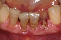
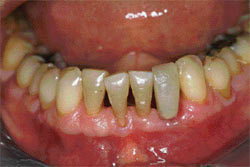
The root was extracted in a straight, upward motion and the area was allowed to mature and fully heal (Figure 1). After primary healing, the 2.2-mm diameter Anew implant was installed without a surgical flap in a routine manner. The CePo™ Center-Point 1.4-mm diameter pilot drill (Dentatus AB) was used to make the osteotomy in the bone to the selected depth-mark on the drill. The depth was extended past the marking, compensating for the approximating thickness of the soft tissue with some additional space that allowed the implant platform to seat firmly in the mucosa over the ridge.
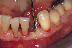
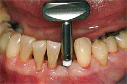
The drill was then used to passively indent the tissue and then drill the osteotomy at 1,500 rpm to 2,000 rpm with copious sterile water past the marked depth on the flutes (Figure 2). The deeper penetration is for compensating the thickness of the mucosa when done without a surgical flap and to prevent bottoming out of an osteotomy that would not allow fully seating the implant, especially in hard 1- and 2-type bone.
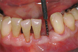
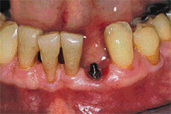
The channel was enlarged with the refining reamer marked on the shank for the 2.2-mm diameter implant to the depth initially created by the pilot drill (Figure 3). The gingival tissue was slightly indented (before installing the implant) to create a seat for the platform and shaping the tissue for a proper emergence profile for the crown.
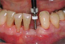
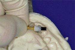
The implant, with the mounted protective silicone sleeve for sealing off open space between the implant platform and the tissue, was initially installed by a few threads with the plastic driver attached to the implant (Figure 4).
The manual winged key was used to complete the installation (Figure 5) and the titanium anti-rotational indexing coping was tightly assembled to the implant platform with the gray, non-hygroscopic resin screw-cap. The coping’s thin uprights, which can be positioned faciolingually or mesiodistally, were firmly attached to the resin to prevent implant rotation during the seating of the crown and reassembly of the screw cap. (It should be noted here that dental resin composites and wax patterns may be directly applied against the screw-cap without lubricants or insulation. The slightly wider gray screw-caps are used in technical procedures. The incrementally slimmer white screw-caps are used to attach the restoration to the patient’s implant.)
A temporary polycarbonate crown was selected to fit into the space, creating a wide lingual opening for seating the crown form over the screw-cap coping assembly (Figure 6). Auto-cure resin was adapted first with finger pressure around the coping assembly and screw-cap, and the crown filled with resin was seated into its predetermined space. (For more precise orientation, a small plaster index can be used during the procedure.) After the polymerization, the screw-cap was disassembled with a counter-clockwise rotation of the manual driver. The patient was instructed to avoid contact with hard edibles for at least 6 weeks and proceed thereafter with normal function. The temporary crown was finished, polished, and reassembled with the white screw-cap. The screw-cap was slightly indented below the crown level and filled with an off-color resin for visible re-access. The elastic protective sleeve was removed with a thin probe instrument in an upward direction with the implant firmly anchored in the bone and surrounded by healthy soft tissue (Figure 7).
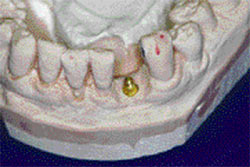
Before taking an impression, the temporary crown was disassembled with the manual driver. The plastic transfer coping was attached with the gray screw-cap to the patient’s implant for indexing its position and taking an elastometric impression in a closed tray (Figure 8). The polymerized impression was removed (leaving the attached transfer coping in place). The transfer coping was disassembled and was firmly reattached to a brass analog with the gray screw-cap and seated into the impression’s precisely keyed position. The master model with the precisely keyed brass analog was used for the construction of the ceramic crown (Figure 9).
The crown was copied from the patient’s fractured tooth and supplied to the technician for matching the color and anatomy according to standard procedures. The crown was firmly attached with the white screw-cap and filled with an off-color resin for future re-access (Figure 10).
CONCLUSION
In spite of careful planning, clinically observed realities at times show that the ideally selected implant sites in the bone may not correspond to the need of aligning the crown for optimal functional and esthetic results. Because compromising the implant position is not an option, the procedure can be modified as follows: The indexing, castable plastic pattern can be used to construct a metal coping in a form similar to the preparations made for cemented crowns. The metal coping can be assembled to the patient’s implant for taking a conventional impression. A ceramic or resin crown can be constructed and cemented over the coping attached to the patient’s implant. More detailed information is available from the manufacturer.
Dentists continue to place wider brand-name implants for patients without physical or financial limitations and who are able and willing to undergo the lengthier procedures. For patients with physical or financial limitations, dentists consider the less-costly, user-friendly narrow-bodied implants a great contribution to dental care.
References
1. Ravasini G, Ugolini G, Dalla Turca F. Protocollo operativo per l’utilizzo di impianti provvisori immediati (Mini Transitional Implants—MTI). Daialog: Rivista Pratica Per IL Team Odontoiatrico. Edizioni Martina Bologna. 1996;1(1).
2. LaBanca M, Mantovani S, Longo M. Mini pins: protesizzazione provvisoria su impianti. Doctor OS Maggio. 1995;6(5):43-45.
3. Gottenhrer NR, Singer G. Full team approach for provisional stabilization of the edentulous patients. Dent Today. 1996;15(1):58-59.
4. Rapani C, Palombo E, Caputi S. Sistema MTI impianti transizionali casi clinici. Dental Cadmos Journali. 1997;44-55.
5. Petrungaro P. Fixed temporization and bone-augmented ridge stabilization with transitional implants. Pract Periodontics Aesthet Dent. 1997;9(9):1071-1078.
6. Froum S, Emtiaz S, Bloom MJ. The use of transitional implants for immediate fixed temporary prostheses in cases of implant restorations. Pract Periodontics Aesthet Dent. 1998;10(6):737-746.
7. Chiche FA. La mise en charge immediate des prostheses transitoires en implantologie orale a l’aide du Systeme MTI. Journal de Parodontologie & d’Implantologie Orale. 1999;18:71-79.
8. Nagata M, Nagaoka S, Mukunoki O. The efficacy of modular transitional implants placed simultaneously with implant fixtures. Compend Contin Educ Dent. 1999;20(1): 39-42.
9. Judy K, Sarnachiaro O, Bonal O, et al. Transitional implant research study. Histology study in nonhuman primates. Primate Research Institute, Oral Implantology Center, Buenos Aires, Argentina, 1996.
10. Zubery Y, Bichacho N, Moses O, et al. Immediate loading of modular transitional implants: a histologic and histomorphometric study in dogs. Int J Periodontics Restorative Dent. 1999;19(4):341-352.
11. Rohrer M. Hard Tissue Research Laboratory, University of Minnesota, School of Dentistry, Division of Oral and Maxillofacial Pathology. Jan/Feb 2001.
12. Simon H, Caputo AA. Removal torque of immediately loaded transitional endosseous implants in human subjects. Int J Oral Maxillofac Implants. 2002;17(6):839-845.
13. Landolt M, Park SH, Galasso D, et al. “Survival Rate of Transitional Implants Supporting Screw Retained Restorations.” International Symposium of Periodontics & Restorative Dentistry. 2004; Boston, MA.
14. Kanie T, Nagata M, Ban S. Comparison of the mechanical properties of 2 prosthetic mini-implants. Implant Dentistry. 2004;13(3): 251-256.
15. Froum S, Simon H, Cho SC, et al. Histologic evaluation of bone-implant contact of immediately loaded transitional implants after 6 to 27 months. Int J Oral Maxillofac Implants. 2005;20(1):54-60.
16. Trushkowsky R. Modular-transitional implants & modular prosthetic system. Esthetic Dentistry Update. 1996;7(2):52-54.
17. Blatz MB, et al. Instruments, materials and equipment. Implantologie. 1996; Albert-Ludwigs Universitat, Freiburg, Germany; Department of Prosthodontics.
18. Bichacho N, Landsberg CJ, Rohrer M, et al. Immediate fixed transitional restoration in implant therapy. Pract Periodontics Aesthet Dent. 1999;11(1): 45-51.
19. Petrungaro P. Reconstruction of severely resorbed atrophic maxillae and management with transitional implants. Implant Dent. 2000;9(3): 271-277.
20. Petrungaro P. “Transitional Implants.” Academy of General Dentistry. 2001;3(1).
21. Brown M, Tarnow D. Fixed provisionalization with transitional implants for partially edentulous patients: a case report. Pract Periodontics Aesthet Dent. 2001;13(2):123-127.
22. Cohen M, Flake R. Special Report 4. The Seattle Study Club Journal. 2001;5(2):32-37.
23. Petrungaro P. Esthetic full-arch transitional appliances, after tooth removal, using the master diagnostic model. Contemporary Esthetics and Restorative Practice. 2001;5(8):54-55.
24. Bucking W. Erste Hilfre bein Totalprothesen. Quintessenz Die Dental Trickkiste. 2002;53(4):1-8.
25. Simon H. Use of transitional implants to support a surgical guide: enhancing the accuracy of implant placement. J Prosthet Dent. 2002;87(2): 229-232.
26. Limbour P, Delanque O, Thepin JC. Les implants modularies provisoires MTI. Implantologie Revue Trimestrielle d’implantologie Oral. 2002;47:75-79.
 |
 |
|
| Figure 1 The root was extracted in a straight, upward motion and the area was allowed to mature and fully heal. | Figure 2 The drill was used to passively indent the tissue and drill the osteotomy past the marked depth on the flutes. | |
 |
 |
|
| Figure 3 The channel was enlarged with the refining reamer marked on the shank for the 2.2-mm diameter implant to the depth initially created by the pilot drill. | Figure 4 The implant was initially installed by a few threads with the plastic driver attached to the implant. | |
 |
 |
|
| Figure 5 The manual winged key was used to complete the installation. | Figure 6 A temporary polycarbonate crown was selected to fit into the space. | |
 |
 |
|
| Figure 7 The elastic protective sleeve was removed with a thin probe instrument in an upward direction with the implant firmly anchored in the bone. | Figure 8 The plastic transfer coping was attached with the gray screw-cap to the patient's implant for indexing its position and taking an impression. | |
 |
 |
|
| Figure 9 The master model with the precisely keyed brass analog was used for the construction of the ceramic crown. | Figure 10 The crown was firmly attached with the white screw-cap and filled with an off-color resin for future re-access. | |
| About the Author | ||
 Tommaso Ravasini, DMD Tommaso Ravasini, DMDPrivate Practice Parma, Italy |
||

