CEREC 3D Software’s Replication Design Mode
Suzette M. Stines
Computer-aided design/computer-aided manufacturing (CAD/CAM) restorative procedures have become commonplace in dentistry today. There are more than 17 laboratory CAD/CAM systems in use.1 There is, however, only one chairside intraoral system in use, the CEREC® 3D (Sirona Dental Systems, LLC, Charlotte, NC). In 1985, Dr. Werner Morman placed the first chairside CAD/CAM restoration, a mesial-occlusal-distal VITA® feldspathic porcelain onlay (Vident™, Brea, CA) with the prototype of the CEREC system.2
The CEREC 1 chairside intraoral CAD/CAM system, introduced in 1987, was able to fabricate posterior inlays. Over the years, the range of procedures possible with intraoral CAD/CAM systems has expanded as the software has evolved and the milling capabilities have advanced. In 1994, with the release of CEREC 2, onlays became possible. A few years later, software was introduced that included crown design mode. With the introduction of CEREC 3 software in 2000, it became possible to copy an existing restoration but it was necessary to align, exactly, sets of data over each other to fabricate a restoration. In the CEREC 3D correlation design mode, an existing tooth or restoration is optically imaged; the tooth is then prepared and imaged. The practitioner can then design a restoration to fit over the prepared tooth.
This ability to exactly copy an existing restoration widened the applications even further. CAD/CAM software will now allow the practitioner to position a remote set of data over a preparation form. The data from the preparation optical impression does not have to match the data from the occlusion optical impression. The occlusion optical impression can be from a different patient, a model, or the contralateral tooth of the same patient. If using an impression of a contralateral tooth from the same patient, the CAD/CAM’s ability to capture the morphology of the patient’s own dentition essentially creates a custom tooth library for the proposed restoration. This application, which can be used to restore small segments of the anterior zone, is quite remarkable in that it provides the opportunity to precisely copy the patient’s dental morphology rapidly and easily, chairside.
The procedure for copying a contralateral tooth is quite straightforward. The contralateral tooth is optically imaged. The tooth requiring restoration is prepared and imaged. The image of the contralateral tooth is flipped or mirrored, positioned over the preparation, and then refined. This replication design mode allows the practitioner to fabricate a restoration that is an exact esthetic match when restoring small segments of the anterior zone. This is extremely useful in restoring a single central incisor or a central and lateral as in the case outlined in this article. By using this design mode, the line angles and incisal edge morphology are exactly duplicated with great ease and rapidity. The CEREC 3D system offers this capability with the replication design mode available in the V2.8 R2400 software.
CASE STUDY
The patient presented with a periapical abscess on tooth No. 7. The patient previously had tooth No. 8 restored with a full gold crown (Figure 1). In the treatment-planning phase, the esthetic reconstruction of teeth Nos. 7 and 8 was presented to the patient with the aid of Practiceworks® Dicom (Kodak, Rochester, NY) cosmetic-imaging software. The patient agreed that the restoration of tooth No. 8 with a ceramic crown would result in an enhanced esthetic appearance. After endodontic treatment and post placement in tooth No. 7, teeth Nos. 7 and 8 were restored with full ceramic crowns. The crowns were fabricated using the replication design mode of the CEREC 3D intraoral CAD/CAM system with V2.8 R2400 software.
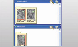
The anterior segment was isolated with a rubber dam, and titanium-dioxide powder was applied to the area as an optical imaging agent (Figure 2). The use of titanium dioxide ensures uniform scattering of the light when taking an optical impression. Without the contrasting agent, some of the light is absorbed into the enamel and some light is scattered by the glare of the field. An optical impression was taken with the digital camera of the CEREC 3D acquisition unit. The optical impression included the area to be replicated; in this case teeth Nos. 9 and 10. This image was stored in the occlusion catalog.
Tooth No. 8 was prepared (Figure 3). One optical impression was taken of teeth Nos. 8 and 9 (Figure 4). The CEREC 3D CAD/CAM software automatically recognized the contralateral central as the tooth to be copied. The design and milling of tooth No. 8 was completed following the same procedures outlined below for tooth No. 7.
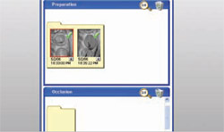
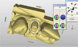
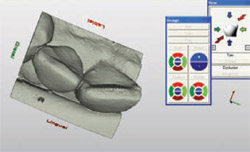
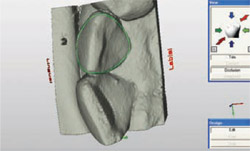
Tooth No. 7 was prepared for a full-coverage ceramic restoration. The completed, milled restoration for tooth No. 8 was placed in the mouth. An optical impression was taken of the preparation of tooth No. 7 (Figure 5). From this data, the replication software developed and displayed a virtual stone model (Figure 6). From this virtual model, the practitioner defined the margin of the restoration. Then the software displayed a different virtual model of tooth No. 10, the tooth to be copied or replicated (Figure 7). The CEREC 3D replication software prompts the practitioner to outline the portion of the tooth to be copied (Figure 8). The replicate can be mirrored or flipped to achieve a suitable mesio-distal orientation for the contralateral side. This allows the replication from the contralateral tooth (Figure 9). A shell of the copied data was superimposed over the preparation form (Figure 10). The practitioner used CEREC 3D’s position and rotate tools, which allow manipulation of the shell proposal in three axes of space (x, y, and z), to properly align the shell in the virtual model of the patient’s arch (Figure 11). The software then automatically filled in the incomplete areas of the restoration to generate a completed proposal of the restoration for tooth No. 7 (Figure 12 and Figure 13). The interproximal contacts were refined as well as the incisal and gingival embrasures.
The completed design was then ready for the milling process. The crowns were milled from 1M2C VITA® Mark II feldspathic porcelain (Vident). The restorations for teeth Nos. 7 and 8 were tried in and the fit was verified. The crowns were stained and glazed with VITA® Stains (Vident). The internal aspect of the restorations were etched with VITA® Ceramic Etch (Vident), silanated with Monobond-S (Ivoclar Vivadent®, Amherst, NY) and bonded into place with Multilink® resin cement (Ivoclar Vivadent). The patient was very satisfied with the esthetic result. The entire procedure was easily accomplished, chairside, in one appointment of about 2 hours (Figure 14).
CONCLUSION
The new CEREC 3D V2.8 R2400 software has expanded the number of design modes available. For more advanced users of the CEREC 3D system, investigating the many applications of some of the newer design modes can be fulfilling in exciting new ways to deliver patient care.
CAD/CAM restorative dentistry has changed over the past 20 years. Improvements in design software have expanded the possible restorative applications from simple inlays to more complicated and esthetic restorative solutions. For more advanced users of intraoral CAD/CAM technology, investigating and mastering some of the newer design capabilities can result in wonderful ways to provide excellent restorative solutions for our patients in one clinical visit.
REFERENCES
1. Morman W, Brandestini M. The Fundamental Inventive Principles of CEREC CAD/CAM. In: State of the Art of CAD/CAM Restorations: 20 Years of CEREC. Mormann WH, ed. Chicago, Ill: Quintessence. 2006; 1-8.
2. Tinschert J. CAD/CAM Systems and Materials for the Dental Lab. In: State of the Art of CAD/CAM Restorations: 20 Years of CEREC. Mormann WH, ed. Chicago, Ill: Quintessence. 2006;139-144.
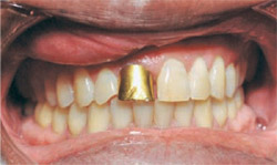 | 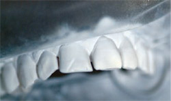 | ||||||
| Figure 1 At presentation, the patient had a periapical abscess on tooth No. 7, and had previously had tooth No. 8 restored with a full gold crown. | Figure 2 After rubber-dam isolation, titanium-dioxide powder was applied to the anterior segment to act as an optical imaging agent. | ||||||
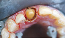 |  | ||||||
| Figure 3 The preparation of tooth No. 8. | Figure 4 An optical impression was taken of teeth Nos. 8 and 9. | ||||||
 |  | ||||||
| Figure 5 An optical impression was taken of the preparation of tooth No. 7. | Figure 6 From the optical impression, the replication software developed and displayed a virtual stone model. | ||||||
 |  | ||||||
| Figure 7 A virtual model of tooth No. 10, which was the tooth to be replicated. | Figure 8 The CEREC 3D replication software prompts the user to outline the part of the tooth to be copied. | ||||||
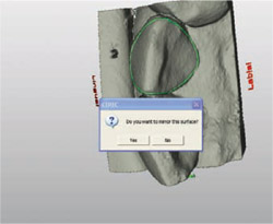 | 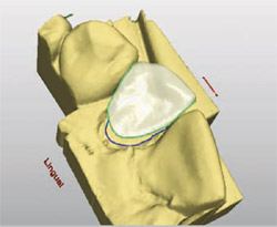 | ||||||
| Figure 9 The replicate can be mirrored or flipped to gain the correct orientation. | Figure 10 The copied data can be superimposed over the preparation image. | ||||||
 | |||||||
| Figure 11 CEREC 3D's position and rotate tools allow the shell proposal to be manipulated in three axes for proper alignment in the virtual model of the arch. | |||||||
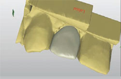 | 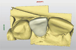 | ||||||
| Figure 12 and Figure 13 The software automatically fills in the incomplete areas of the restoration to generate a completed proposal of the planned restoration. | |||||||
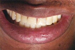 | |||||||
| Figure 14 Using the CEREC 3D system, the entire procedure was completed in one 2-hour visit. | |||||||
| |||||||