You must be signed in to read the rest of this article.
Registration on CDEWorld is free. You may also login to CDEWorld with your DentalAegis.com account.
When first introduced to dentistry, CAD/CAM machines created small and simple inlay/onlay restorations that were synonymous with lower-quality esthetics and open margins. Those shortcomings limited the technology’s use to dental schools, and mostly as a teaching resource. Today, however, a variety of computer-aided-design and computer-aided-manufacturing (CAD/CAM) applications are now available, including digital impression systems, courtesy of computer technology and software advancements.1 This digital evolution has enhanced dental restoration production to include CAD/CAM veneers, crowns, and bridges that can be fabricated chairside, and in one patient visit.2
The first same-day chairside CAD/CAM software was introduced in 1985 by Mörmann with the development of the CEREC (Sirona, www.sirona.com) system, which enabled dentists to create restorations within the dental practice by measuring the prepared cavity with an intra-oral camera, designing the restoration with a computer, and machine milling an inlay from a ceramic block.3-5 Andersson later developed the NobelProcera® CAD/CAM system (Nobel Biocare, www.nobelbiocare.com),6 which utilized CAD/CAM technology to fabricate titanium copings through spark erosion to improve precision casting of titanium as an alternative to gold alloy-based restorations.5
After nearly 30 years of innovation, current chairside CAD/CAM systems represent highly accurate, efficient, and predictable fabrication tools.7 Frameworks demonstrate a superior and more consistent passive fit than conventionally cast frameworks,8 and fabrication requires fewer necessary steps than conventional casting techniques (eg, waxing, investment, casting, and polishing).9 Research indicates that the long-term survival rates for CAD/CAM single-tooth restorations are similar to conventional single-tooth restorations.10
Additionally, CAD/CAM’s integration of new materials, reduced labor, cost effectiveness, and quality control offer several other advantages.5,11 For example, compared to earlier technologies, today’s variety of dental CAD/CAM software and hardware systems,12 combined with advanced metal-free materials, allow dentists to design better restorations that can be milled with greater precision for an enhanced fit. However, CAD/CAM systems vary in their capabilities, with each demonstrating distinct advantages and limitations.13
CEREC, the first chairside CAD/CAM system,14 quickly fabricates laboratory-grade chairside tooth-colored restorations (eg, full-coverage crowns, inlays/onlays, veneers) with rapid digital impression taking, simple designing, and precise machining for improved workflow and efficiency.14-16 The system’s broad spectrum of applications automates the design process for creating patient-specific restorations with easy-to-use and highly predictable and accurate software facilitating preparation and impression monitoring, so temporary restorations or conventional impressions are unnecessary.16
CEREC simplifies and enhances restoration design with such software features as the biogeneric process, which analyzes morphologic characteristics of existing teeth and expresses them as a 3D image rendering.16 Based on the observation that a patient’s teeth exhibit similar morphologic characteristics, Mehl and Blanz developed this approach to create a valid quantitative process for calculating 3D averages of tooth surfaces, representing a principal component in evaluating the natural shape deviations from the 3D average for quickly designing restorations.17
Planmeca (formerly known as the E4D Dentist System, E4D Technologies, www.e4d.com) was introduced in 2008 to offer unique and open interfaces between its devices and software. This feature allows clinicians or the laboratory to choose certain aspects or the entire workflow solution (ie, intraoral scanner, CAD software, and milling machine) according to their needs.18,19 Ideal for designing a variety of restorations (eg, inlays, full-arch bridges, and abutments), the Planmeca system also facilitates same-day and chairside dentistry with its extensive restorative design library and milling capabilities.18
Other companies also provide CAD/CAM restorative solutions (eg, CS Solutions, Carestream, www.carestreamdental.com; 3Shape™ Scan & Design System, 3Shape, www.3shape.com) ranging from complete systems (ie, scan, design, and milling components) to those featuring an oral scanner and design software only, or software and milling machinery (eg, iTero®, Align Technology, Inc., www.aligntech.com; 3M™ True Definition Scanner, 3M™ ESPE™, www.3mespe.com). As the popularity and prevalence of CAD/CAM technology and same-day dentistry continue to grow, more product developments for CAD/CAM use are expected.
Caveats for CAD/CAM Impression Techniques
Because the CAD/CAM restorative process is inherently digital, the digitalization of impressions through intraoral scans has provided clinicians with greater control and instant feedback during this process.20 Digital impressions represent a welcome alternative to conventional impression-taking methods, reducing the need for remakes and patient discomfort and improving delivery time, simplicity, and efficiency.20,21 Several of the steps necessary for conventional impressions (eg, tray selection, disinfection, shipping) are eliminated, and digital impression scanning can typically be completed in less than 5 minutes, which is approximately the same time required for conventional materials to set.20 Patients are more accepting of a comfortable digital impression process, which also decreases occurrences of material distortion and, therefore, the likelihood of restoration remakes.22,23
Original digital intraoral scanners required powder to accurately capture images of oral structures, and early scanning systems required the use of titanium dioxide as an antireflective coating prior to taking optical impressions.24 Many updated scanners today are powderless, eliminating the additional step, further increasing patient comfort, and improving efficiency.
However, to avoid the expensive upfront costs associated with digital impression scanners, clinicians continue to rely on conventional impressions to provide an accurate representation of the oral cavity. Successful conventional impression taking requires moisture control, atraumatic tissue retraction, clean tooth preparations, avoidance of material tears or distortion, and adequate disinfection and durability after removal.25 These requirements alone—as well as an in-vitro study indicating that digital impression accuracy is similar to that of conventional impressions—may encourage clinicians to invest in digital systems.26
Material Options for CAD/CAM Restorations
One factor limiting application of early CAD/CAM technology was the restorative ceramic blocks.7 The original CEREC system first utilized the Vitablocs Mark I (VITA Zahnfabrik, www.vita-zahnfabrik.com) ceramic material, a feldspar-based, fine-particle ceramic compressed into a block, machined, and then milled to create a restoration.14 In 1987, Vitablocs Mark I was replaced with Vitablocs Mark II (VITA Zahnfabrik),27 a fine-grained, high-glass-content feldspar-based ceramic used until about 1997.14
As an alternative to porcelain, Paradigm™ MZ100 blocks (3M ESPE), filled (85%-90%)with ultrafine silica ceramic particle embedded in a bisphenol A-glycidyl methacrylate resin matrix, were introduced in 1997.14 Subsequent CAD/CAM material advancements have included lithium disilicate glass ceramic (IPS e.max® CAD, Ivoclar Vivadent) introduced in 2006, and the CEREC block (Sirona) launched in 2007.14
Over the past 30 years, manufacturers have developed and introduced higher quality materials for use with CAD/CAM restorative systems that demonstrate enhanced esthetics, strength, and millability.7,13 These are typically manufactured in a uniform solid block in preparation for the milling process.7 Most CAD/CAM systems utilize a wet grinding process for milling or shaping the material blocks into restorations, and generally the material must be milled in less than 20 minutes to deliver same-day restorations.7
CAD/CAM Restoration Design Considerations
Despite more widespread use, many clinicians remain intimidated by completing CAD/CAM anterior restorations due to the necessity of matching the line angles, emergence profile, incisal edge position, and surface texture of adjacent teeth. However, three viable techniques can be used to design highly esthetic and functional anterior restorations.
1. Biogeneric Copy
The biogeneric copy technique is the easiest and most common method for designing anterior restorations. It utilizes an exact copy of the existing tooth contours and is primarily used when the preoperative tooth shade, size, form, and position are desirable for replication in the final restoration. Indicated for designing restorations to replace/treat pre-existing crowns, veneers with recurrent decay, and discolored teeth, this technique works well for creating restorations based on an already established ideal shape. It can also be used in complex cases where the laboratory fabricates a wax-up for multiple teeth. The biogeneric copy provides an easy and predictable way to design multiple restorations, as it involves simply copying the old tooth or restoration form, with the software replicating the design to create a new restoration. A few tools and minor modifications may be necessary during the design stage to ensure optimal occlusion and esthetics.
Case Study 1
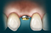
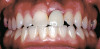
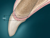
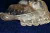
A patient presented with veneers on teeth Nos. 7 through 10, with the No. 9 veneer fractured and a piece saved (Figure 1). After initial assessment, the patient requested same-day dentistry to replace the fractured veneer. The broken piece was placed back onto the tooth with adhesive and tack cured to create an acceptable and desired proposed shape for the final veneer. A scan was then taken of teeth Nos. 6 through 11, placed in the “BioCopy Upper” folder, and also copied into the “Upper Arch” folder. The scan was cut using the cut tool, and a void was left behind.
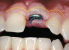
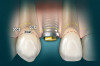
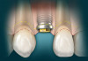
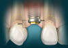
The veneer on No. 9 was then completely removed and the tooth prepared. A scan of the preparation was taken and placed into the “Upper Arch” folder (Figure 2). The software was used to marginate the preparation, and the insertion axis was established for the new restoration. A line was drawn around the entire tooth No. 9 surface (Figure 3) to include the line angles and incisal edges, and the software proposed a restoration design exactly replicating the preoperative contours and shape (Figure 4). Minor modifications were completed using the form smooth tool on the proposed veneer (Figure 5). The proximal contacts were then verified, and the veneer was milled from a lithium disilicate block (IPS Empress® CAD Multiblock, Ivoclar Vivadent). The fit of the veneer was verified intraorally (Figure 6), after which it was polished with a bristle brush (Abbott-Robinson® Brush, Buffalo Dental Manufacturing Co., Inc., www.buffalodental.com) and polishing paste (DiaShine Fine, VHTechnologies, www.vhtechnologies.com), then seated using dental adhesive (OptiBond™ XTR, Kerr Dental, www.kerrdental.com) and resin cement (NX3 Nexus, Kerr Dental) (Figure 7).
2. Biogeneric Reference
Utilized when a tooth requires restoration but the existing shape, size, form, and/or position is not desirable, the biogeneric reference method generates a computer-controlled match of the contralateral tooth as the restoration design. Typically used for single anterior tooth restorations, the designs are based on shapes of teeth in the same class (ie, if tooth No. 9 were broken and required restoration, the shape of tooth No. 8 would be replicated for the restoration). Similar to the biogeneric copy method, the software uses an already existing tooth shape for restoration design.
Case Study 2
A patient presented with a fractured porcelain crown, recurrent decay, and previously placed cast gold endodontic post on tooth No. 9 (Figure 8). After all treatment options were considered, the patient chose to replace the fractured crown. Because the shape, size, and form of tooth No. 9 were undesirable and the biogeneric copy method inappropriate, tooth No.8 would be used as a biogeneric reference and model for the final restoration.
All decay was removed from tooth No. 9, the margins were refined, and enameloplasty was completed on the worn incisal edge to improve esthetics. The preparation and adjacent teeth were scanned into the “Upper Arch” folder (Figure 9), and the opposing teeth were scanned into the “Lower Arch” folder (Figure 10). The patient was then instructed to close into maximum intercuspation, and the bite relation was captured in the “Buccal Bite” folder. The software then combined the three scans, mimicking the patient’s maximum intercuspation (Figure 11).
The software then marginated tooth No. 9, the correct insertion axis was chosen, and tooth No. 8 was replicated as the final restoration for No.9. Tooth No. 9 was then selected in the upper teeth scan. Similar to the biogeneric copy method, the copy line was drawn around the entire surface of tooth No. 9 and adjusted to include line angles and the incisal edges. The software then proposed an exact replica of the form, shape, and size of tooth No. 8 as the restoration for tooth No. 9 (Figure 12).
The crown was then milled from a lithium disilicate block (IPS e.max® LT, Ivoclar Vivadent) to mask the dark stump, and then tried in intraorally to verify the margins and contacts. It was then stained, glazed, and seated using and dental adhesive (OptiBond XTR) and resin cement (NX3 Nexus) (Figure 13).
3. Biogeneric Individual
The last resort for anterior teeth, this method is used only when neither the tooth to be restored nor the contralateral tooth has a desirable shape, size, or form. This technique analyzes neighboring and adjacent teeth, then calculates and proposes a restoration design that fits the form and shape of the other teeth in the arch; the more information available, the more successful the calculation. While predictable for posterior teeth, this method requires more modifications for anterior teeth using design tools after the initial software design is proposed. This increases the time necessary to design a restoration and requires additional knowledge of various design tools.
Case Study 3</p>
A patient presented with fractured incisal edges on teeth No. 8 and 9, with wear and diastemas between them (Figure 14). The patient’s chief desire was an even-looking smile without the dark triangle between teeth Nos. 8 and 9, and she wanted the dentistry completed in one visit. Without this request, an impression could have been sent to the laboratory for creating an ideal wax-up, which would then have enabled the biogeneric copy technique. Unfortunately, neither of the teeth to be restored demonstrated ideal form or shape, and none of the other teeth in the arch provided an ideal replicating template.
The teeth were prepared for veneers, and along with the adjacent teeth, were scanned into the “Upper Arch” folder while the opposing teeth were scanned into the “Lower Arch” folder. The patient was instructed to bite into maximum intercuspation, and the bite relation was captured in the “Buccal Bite” folder. The software then compiled the three scans to mimic the patient’s bite in maximum intercuspation (Figure 15).
In the model phase, teeth Nos. 8 and 9 were marginated and the correct insertion axis selected. The software then proposed veneers for No. 8 and No. 9, but the restoration width, incisal edge position, and basic outline form designs did not match (Figure 16). CAD software tools were utilized to alter the veneer designs and create harmonious restorations (Figure 17). Once the form, shape, and size of the veneer designs were identical, the incisal variation tool was used to impart anatomy and texture to the facial surfaces.
The veneers were then milled with blocks featuring an inherent color gradation to match the other teeth in this case (VITA TriLuxe, VITA Zahnfabrik). After the fit was verified, the restorations were polished with a bristle brush (Abbott-Robinson Brush) and polishing paste (Diashine Fine), then seated with dental adhesive and resin cement (Figure 18).
Multi-Visit, Full-Arch Rehabilitation: Case Study 4
A patient presented with chief complaints of an uneven smile, discolored teeth, and overall unhappiness with his current smile (Figure 19). A smile analysis was completed, and preoperative photographs and a polyvinyl impression of his upper and lower arches were sent to the laboratory for fabrication of an ideal wax-up with golden proportions. The laboratory was instructed to increase the length of tooth No. 8 by 1.5 mm and finish the others based on those proportions (Figure 20). The laboratory also fabricated a clear stent for provisionalization.
The patient returned, teeth Nos. 5 through 12 were prepared for full-coverage crowns, and the preparations were scanned into the “BioCopy Upper” folder (Figure 21). The clear stent transferred the ideal wax-up to the mouth via provisionals, and after cementation, all eight temporaries were scanned into the biogeneric copy “Upper Arch” folder (Figure 22).
All the teeth were marginated and the correct insertion axis established for each tooth individually. The software then proposed the final eight restorations based on the copy line completed for each individual tooth. The crown designs were modified using the different tools, and ideal embrasures, line angles, and contacts were created (Figure 23). All restorations were milled from light translucency lithium disilicate blocks (IPS e.max LT BL1, Ivoclar Vivadent), which would block the dark tetracycline tooth stains. The restorations were glazed, then tried on the model to verify fit and contacts.
The patient returned again, and the provisionals were removed and the CAD/CAM crowns tried in intraorally to verify margins and contacts. The restorations were adhesively cemented, and the patient was very pleased with the color and even proportions of his smile (Figure 24).
Conclusion
Regardless of the variety and breadth of CAD/CAM systems available today, the technology can alter the way dental professionals design and create restorations. With improved materials and continued technological advancements, digitally designed and milled restorations can be highly esthetic, longer lasting, and more predictable. Additionally, the processes associated with CAD/CAM restorations reduce patient discomfort, improve restorative accuracy, and contribute to efficient practice productivity. Contributing to these advantages are techniques for designing restorations within CAD software. Using an existing tooth form (eg, tooth to be restored, contralateral, or patterns of adjacent teeth) as the basis, today’s dental CAD techniques simplify the design process, leaving the operator only to adjust it to improve esthetics and/or fit.
Disclosure
The author has no relevant financial affiliations to disclose.
Author Information
Dr. Patel has been using CAD/CAM technology for 7 of his 10 years in practice.
References
1. Fasbinder DJ. Computerized technology for restorative dentistry. Am J Dent. 2013;26(3):115-120.
2. Van Noort R. The future of dental devices is digital. Dent Mater. 2012;28(1):3-12.
3. Mörmann WH, Brandestini M, Lutz F, et al. Chairside computer-aided direct ceramic inlays. Quintessence Int. 1989;20(5):329-339.
4. Mörmann WH. The evolution of the CEREC system. J Am Dent Assoc. 2006;137 (suppl 1):7S-13S.
5. Miyazaki T, Hotta Y, Kunii J, et al. A review of dental CAD/CAM: current status and future perspectives from 20 years of experience. Dent Mater J. 2009;28(1):44-56.
6. Andersson M, Odén A. A new all-ceramic crown. A dense-sintered, high-purity alumina coping with porcelain. Acta Odontol Scand. 1993;51(1):59-64.
7. Fasbinder DJ. Materials for chairside CAD/CAM restorations. Compend Contin Educ Dent. 2010;31(9):702-709.
8. Abduo J, Bennani V, Waddell N, et al. Assessing the fit of implant fixed prostheses: a critical review. Int J Oral Maxillofac Implants. 2010;25(3):506-515.
9. Lin WS, Harris BT, Zandinejad A, et al. Use of digital data acquisition and CAD/CAM technology for the fabrication of a fixed complete dental prosthesis on dental implants. J Prosthet Dent. 2014;111(1):1-5.
10. Wittneben JG, Wright RF, Weber HP, et al. A systematic review of the clinical performance of CAD/CAM single-tooth restorations. Int J Prosthodont. 2009;22(5):466-471.
11. Beuer F, Schweiger J, Edelhoff D. Digital dentistry: an overview of recent developments for CAD/CAM generated restorations. Br Dent J. 2008;204(9):505-511.
12. Liu PR, Essig ME. Panorama of dental CAD/CAM restorative systems. Compend Contin Educ Dent. 2008;29(8):482-488.
13. Strub JF, Rekow ED, Witkowski S. Computer-aided design and fabrication of dental restorations: current systems and future possibilities. J Am Dent Assoc. 2006;137(9):1289-1296.
14. Poticny DJ, Klim J. CAD/CAM in-office technology: innovations after 25 years for predictable, esthetic outcomes. J Am Dent Assoc. 2010;141 Suppl2:5S-9S.
15. Hehn S. The evolution of a chairside CAD/CAM system for dental restorations. Compend Contin Educ Dent. 2001;22(6)(Suppl 1):4-6.
16. Ender A. CEREC basic information 4.0: A clinical guide. New York, NY: Sirona Dental Systems GmbH; 2012. http://www.sirona.com/en/products/digital-dentistry/cerec-chairside-solutions/?tab=245. Accessed December 30, 2014.
17. Mehl A, Blanz V, Hickel R. A new mathematical process for the calculation of average forms of teeth. J Prosthet Dent. 2005;94(6):561-566.
18. Planmeca’ modular PlanScan™ offers the ultimate in scanning flexibility. Compend Contin Educ Dent. 2014;35(3):212.
19. Feurstein P. Shakin’ all over. Dent Economics. 2013;103(7):60.
20. Kugel G. Impression-taking: conventional methods remain steadfast as digital technology progresses. Compend Contin Educ Dent. 2014;35(3):202-203.
21. Burgess JO, Lawson NC, Robles A. Comparing digital and conventional impressions. Inside Dentistry. 2013; 9(11):68-74.
22. Christensen GJ. Impressions are changing: deciding on conventional, digital or digital plus in-office milling. J Am Dent Assoc. 2009;140(10):1301-1304.
23. Birmbaum NS, Aaronson HB. Dental impressions using 3D digital scanners: virtual becomes reality. Compend Contin Educ Dent 2008;29(8):494-505.
24. Kurbad A. The optical conditioning of CEREC preparations with scan spray. Int J Comput Dent. 2000;3(4):269-279.
25. Mandikos MN. Polyvinyl siloxane impression materials: an update on clinical use. Aust Dent J. 1998;43(6):428-434.
26. Ender A, Mehl A. Full arch scans: conventional versus digital impressions—an in-vitro study. Int J Comput Dent. 2011;14(1):11-21.
27. Fasbinder DJ. Clinical performance of chairside CAD/CAM restorations. J Am Dent Assoc. 2006;137(Suppl 1):22S-31S.