You must be signed in to read the rest of this article.
Registration on CDEWorld is free. You may also login to CDEWorld with your DentalAegis.com account.
Adhesive dentistry has brought many changes in the waya dentist provides a restoration. Although the changes seem to demand more technical expertise, there is a vast difference from the days when drilling out decay, placing a matrix band, and plugging the hole with amalgam was the norm. With respect to posterior crowns, the trend has gone from an all-metal crown to ceramo-metal to, now, all-ceramic. This trend could not have happened without adhesive bonding technology. Generation after generation of new adhesive bonding systems have kept practicing dentists constantly changing their protocol for placing restorations. Manufacturers vying for market share will continue to bring new ideas and techniques to the restorative practice.
Bonding philosophies have changed over the years from being solely enamel-dependent to the development of systems that rely on the dentin as an additional viable adhesive substrate. The one step in the entire restorative process that has not received much attention is the design of the posterior all-ceramic tooth preparation. The restorative process includes identification of the pathology, proper preparation of the tooth to receive the restoration, and diligent insertion of that restoration. Technology has provided added tools in the caries identification process, and newer bonding adhesives have reduced the technical expertise required to place a sensitive-free restoration, but the tooth preparation has been somewhat overlooked. Most posterior crown preparations today are still based on antiquated cementing techniques. The traditional resistance form and retention form provided by axial wall reduction is still in the minds of dentists while they prepare a posterior tooth for a crown. This is where the confusion lies. Cemented crowns need resistance and retention form while adhesively retained crowns need enamel.1 The tooth preparation should be designed for the restorative material planned and the retentive material that will be used for placement, as opposed to the restorative and retentive materials adapting to the tooth preparation. Removing only the pathology from a tooth and replacing the missing parts of the tooth with a ceramic or industrial-composite material should be a consideration. This would result in less tooth structure likely being removed. The non-retentive, full-coverage “table-top” preparation for posterior metal-free restorations should be considered.
Requirements for an All-Ceramic, Adhesively Retained Restoration
There are a number of factors to consider when planning an all-ceramic or industrial-composite restoration. First, the adhesive potential1 and the amount of enamel should be considered. The size of the existing restoration and the extent of the pathology should be evaluated to determine the amount of remaining enamel that can be used for adhesive retention. Second, the functional environment must be assessed, examining it for any parafunctional activity and the occlusal forces that are present must be examined.2,3 The location of the tooth in the arch (bite forces increase the further posterior the tooth),4 the type of occlusal pattern, and the steepness of the incline planes of the adjacent teeth also must be considered. The generation of lateral stresses may be detrimental to the adhesion portion of the restoration especially if the patient demonstrates significant parafunctional activity. Antagonistic wear must be considered. An industrial (CAD/CAM block) or laboratory-processed composite or an all-metal restoration may be more effective in the long term.5 Third, determine if there will be adequate isolation, which is critical to the success of adhesive bonding.6 Fourth, gauge the ability of the ceramic (composite) material to match or blend in with the inherent tooth shade.7 Lastly, consider the patient’s desire and acceptance of the informed consent presented.
Incidence of Cusp Fractures
It is not uncommon to find fractures at the axial-pulpal line angles after removal of a large MOD amalgam. In fact, Fennis et al8 found in the Dutch population fractured cusps occurring at a rate of 20.5 per 1000 examined. His group found that the incidence was associated (77%) with three or more restored surfaces and the occurrence was found more in molars (79%) than premolars (21%). Maxillary molars presented more fractures of buccal cusps (66% versus 34%), while mandibular molars presented more fractures of lingual cusps (75% versus 25%). Bader et al9 found in their study of restored posterior teeth two clinical features that were strongly associated with the risk of cusp fracture. The proportional size of the restoration and the presence of a fracture line were indicators for posterior fractures. The type of direct restorative material does not seem to play a role in the increased occurrence of previously restored posterior teeth. Wahl et al10 did not find a significant difference in the number of cusp fractures in teeth restored with amalgam versus composite, although in the general practice it may seem more fractures are found associated with amalgam-restored than composite-restored teeth. The fact that amalgam restorative has been in service longer and more teeth have been restored with amalgam may account for this observation.
According to Agar and Weller11 and Abou-Rass12 asymptomatic cracks that are identified with direct vision and transillumination are precursors to cracked tooth syndrome and tooth fracture. Ratcliff et al13 proposed a classification of types of cracks in teeth. Type I included cracks in posterior teeth with no restoration present, no stain in the cracks, and were asymptomatic. Type II included cracks in posterior teeth with Cl I or Cl II restorations, no stain in the crack, and exhibit no symptoms. Type III included stained cracks (detectable with an explorer) with either no restoration, or Cl I or Cl II with no symptoms other than mild sensitivity to sweetness and/or temperature. Type IV included cracks that produce “bite and release” pain and thermal and sweetness sensitivity (cracked tooth syndrome). This study also concluded that it is possible for these cracks to look like Type I, II, or III cracks.
Traditional Crown Preparation Versus “Table-Top” Preparation
Many clinicians were taught full-crown preparation principles that included resistance and retention form gained from axial wall reduction. These principles were taught before the advent of adhesive dentistry. A paradigm shifthas occurred in the preparation requirements for adhesively retained all-ceramic crowns. Some dentists may be reluctant to fully accept the retention strength of adhesives and feel that their crown preparations must still include the retention and resistance form principles that were ingrained into them while in dental school. Traditional crown preparations actually remove the tissue—enamel—a material with which adhesion works so well. A split section of an intact molar will show from an axial perspective that there is a wide band of enamel located in the supra-bulge area approximately halfway down the clinical crown while the thinnest amount of enamel is located at the gingival margin. Therefore, traditional crown preparation that includes axial reduction will actually reduce the surface area of enamel, decreasing the bond strength of the restoration that is gained by the enamel substrate.1 An alternative approach to the traditional crown preparation is non-retentive, adhesively retained “table-top” crown preparation. In select cases, it allows for maximum preservation of the enamel, reducing the amount of tooth preparation and creating more supra-gingival margins. Therefore, the “table-top” preparation actually increases the amount of surface area of bondable enamel, thus increasing the bond strength of the restoration to tooth substrate.
Studies show that the adhesive substrate does have an influence on the fracture resistance of ceramic restorations.15 There is higher fracture resistance for ceramic restorations that are bonded with resin to enamel versus those bonded to dentin.16-18
Tensile stress is the predominant factor controlling the initial failure of ceramics. The critical tensile stress is dependent on the elastic modulus mismatch of the ceramic, cement, and supporting material.19 Rekow et al used a series of finite element models of an axisymmetric stylized ceramic crown-cement-tooth system in their factorial analysis on the variables that influence the stress in all-ceramic crowns. They concluded that the crown material and thickness were the primary importance in stress magnitude, but other variables (cement modulus, load position, and supporting tooth core) also contribute to the stress magnitude.20
“Table-Top” Preparation Technique
When a tooth has been treatment planned for a full-coverage restoration, a traditional crown preparation is usually the procedure of choice. Kois states that cases that require cuspal protection but still maintain significant structural integrity in an axial dimension may be suited for an adhesively retained restoration.1
The following steps show the progression of the “table-top” preparation for a typically encountered molar with a large 3-surface amalgam and that has been diagnosed with “cracked tooth syndrome.” For instructional purposes, in this article the steps are performed on a dentaform model. Understanding that this media represents the ideal scenario will give the reader a better visual of the steps involved using this particular preparation sequence. Whether to cover the cusp or not is a clinical decision. However, in their study, Krifka et al found that thin non-functional cusp walls of adhesively bonded restorations should be completely covered or reduced to avoid enamel cracks and marginal deficiency.21 As a general rule, cuspal coverage may be indicated where the remaining tooth structure is less than one-third to one-half of the intercuspal distance.1,22
In addition to advocating the one-third/one-half rule, Christensen23 also warns the clinician to consider other factors. These include the presence of horizontal cracks in the tooth structure, a lack of supporting dentin under the cusp, the presence of a heavy occlusion, and highly discolored cusps in esthetically important areas. He also feels that patients who have a history of eating hard foods should not be left with an unprotected questionable cusp.
The minimal thickness of all-ceramic restorations should be at least 2 mm and follow the topography of the occlusal anatomy. The head length of a standard #330 carbide bur is 2 mm and can be used as a depth cutter in all areas of the tooth. The first step is to take a #330 carbide bur, place it in the central fossa, and drill down into the existing restoration until the hilt (where the head and the shank meet) is level with the occlusal surface of the restoration (Figure 1). From here, the bur is moved through the buccal groove until it cuts through the buccal wall of the tooth and then to the lingual side through the lingual groove (Figure 2). The bur is then moved from the central fossa to the mesial marginal ridge and back through the restoration to the distal marginal ridge. A cross-pattern depth cut of 2 mm can now be observed from the occlusal aspect (Figure 3).
The next step is to remove all of the cusps to the level of the cross-pattern occlusal depth cut. The #330 carbide bur or a #169L carbide bur can be used. Keeping the shank of the bur parallel with the pulpal floor, a cut is made under the entire mesial–buccal cusp starting at the buccal groove to the mesial marginal ridge depth cut (Figure 4 and Figure 5). The bur is then moved back to the buccal groove and directed to the distal marginal depth cut, which removes the entire distal–buccal cusp (Figure 6). The handpiece is then positioned on the lingual aspect of the tooth and both the mesial and distal–lingual cusps are removed (Figure 7).
At this point a minimum of 2 mm clearance has been provided for the ceramic material. If any of the existing restorative material still remains, it is then removed with a modified shoulder diamond bur. This removal will add to the final thickness of the all-ceramic restoration and also create an isthmus that will provide orientation as a positive seat insertion of the restoration (Figure 8). If there is no remaining restorative material an isthmus should still be provided for orientation purposes.
Interproximal Area
The interproximal areas become involved when there is an existing restoration, fractures, or caries. Using the same diamond bur, the restorative material is removed from the mesial and distal interproximal box areas. This step lowers the interproximal margins in a more cervical direction and also provides further orientation guidance for seating the restoration.
In cases where there is no interproximal restorative material present and the contact is still intact after the 2-mm reduction is completed, a decision must be made to either break the contact or leave it intact. From a laboratory standpoint or if a chairside digital scanner is being used to acquire the image of the preparation, breaking the contact will enhance the ability to locate the margin. A #7801 12-fluted finishing bur is used to break the interproximal contact (Figure 9). The bur is placed on either the buccal or lingual side and swept through the contact area. The thickness of this size bur provides sufficient room for impression material or a scanable view with a digital acquisition camera. The outer contour of the tooth will be flattened as the bur is passed through the interproximal space as irregularities in the anatomical form are eliminated. The flat margin enhances the margin tracing in a digital scenario as well as a traditional laboratory setting.
An end-cutting diamond bur is then used in the interproximal box area to eliminate any abrupt dimensional vertical/horizontal platform-to-wall transition changes (Figure 10). Sharp line angles tend to accumulate stress and should be avoided.23 Rounded internal line angles minimize stress concentrations.24,25
An inverted cone diamond bur can be used to place further orientation grooves between the isthmus and the outer buccal and lingual occlusal tables (Figure 11). These added orientation grooves will help in the final seating of the restoration and contribute to the blending of the ceramic-to-tooth esthetic transition. The change from a flat occlusal platform to a varied platform helps create a chameleon or “contact lens” effect where the ceramic material accommodates the shade of the tooth.26
As previously stated, the ceramic thickness is critical to the success of the restoration. A 2-mm flexible clearance tab can be placed over the occlusal surface of the prepared tooth and the patient instructed to close into centric occlusion. If sufficient reduction has been provided, the flexible tab should easily pull through. Any resistance encountered is then identified and corrected.
The last preparation step is to use a tapered finishing bur over the entire prepared tooth surface (Figure 12 and Figure 13). This is done for two reasons. First, carbide finishing burs will produce a smoother surface compared to a diamond bur.27 A smooth, rounded prepared tooth surface reproduces better with all impression materials and die stones.28,29 Also, a smooth margin is easier to read on a digitally scanned virtual model (Figure 14 and Figure 15).
Secondly, coarse diamonds produce a thick, uneven smear layer, whereas carbide burs produce a thin, even smear layer.30 The significance in the different smear layers is pertinent when a self-etching adhesive is to be used. Yiu et al30 found higher bond strengths were achieved with a self-etching adhesive when it was applied on dentin surfaces that had been prepared with carbide burs. There was less penetration of the milder acids contained in self-etching adhesives through the thicker, more uneven smear layers produced by diamond burs. The thicker smear layers also had more of a buffering or neutralizing effect on the milder acids. Barros et al31 found in their study that carbide burs leave a surface that is more conducive to bonding than diamond burs.
After this step, gingival retraction is initiated wherever necessary. This can be done with either a non-impregnated retraction cord or a diaode laser. If using the traditional two-appointment method, the exposed dentinal tubules should be sealed prior to the impression step or digital scanning.32 A one-step, two-step, or three-step method of applying a dentin adhesive can be used. It is imperative that the oxygen-inhibited layer be removed by applying a water-soluble clear gel over the resin-coated prepared tooth and light-polymerized. It is recommended that pumicing of the sealed surface be completed prior to taking the impression.33 If an in-office one-appointment milling method (eg, CEREC, Sirona Dental Systems, Inc, www.sirona.com or E4D, D4D Technologies, www.e4dsky.com) is used, then the sealing step is omitted and the prepared tooth can be digitally scanned.
Provisional Restorations
Provisional restorations are only necessary for the two-appointment method. In these cases, since the dentinal tubules have already been sealed, postoperative sensitivity is not an issue. The purpose of the provisional at this point is to maintain the positions of the adjacent and opposing teeth. Composite material can be placed using either a free-hand technique or a vacuum-formed stent from a preoperative model. Retention is gained from the interproximal undercuts from the adjacent teeth and by extending the provisional material into the undercut area below the buccal and lingual margins.
Ceramic Preparation for Bonding
The bonding mechanism of a resin to a ceramic surface is a combination of the effects of micromechanical interlocking and chemical bonding.34 There are numerous articles addressing the various methods of conditioning the intaglio ceramic surface for bonding purposes. Micromechanical interlocking is created by acid or sand-air abrasion or roughening the surface with a diamond bur. Each of these methods creates microporosities and increases the surface area. However, overuse of each of these methods can create surface flaws leading to crack initiation.35-37 Strong micromechanical bonds are formed as the resin flows and interlocks into the porosities.
The bond strength of the chemical bond between the resin and the ceramic is affected by the silane coupling agent.38,39 Hydrofluoric acid has been the most commonly used acid to obtain microporosities through etching of glass surfaces.40 It is imperative to seek out the manufacturer’s recommendations for bonding resin to their ceramic. This information would also include the type of acid they recommend as well as the concentration and the etching time.
The alternative is phosphoric acid in combination with a ceramic primer. The phosphoric acid is applied for 5 seconds and rinsed with water. The primer is then applied with a microbrush to the intaglio surface and can be immediately air-dried.
Insertion
The insertion steps differ somewhat depending on whether a one- or two-appointment procedure was used. Both techniques require strict isolation either with a rubber dam or some other system that ensures a dry field. For the one-appointment technique, the manufacturer’s recommended protocol for a three-step, two-step, or one-step dentinal adhesive system should be followed. For the two-appointment technique, after removal of the provisional restoration, the prepared surfaces should be lightly air-abraded to ensure a clean bonding surface. The recommended steps for whatever adhesive system is chosen are followed. The occlusion should only be checked after the restoration has been bonded to the tooth. Any adjustments should be finished with a series of diamond-impregnated points and polished with a bristle brush and diamond paste.
Clinical Case
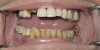
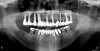
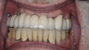
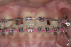
This clinical case shows some of the preparation steps previously illustrated. The patient presented with a chipped distal–buccal cusp of the lower right first molar. There was a large 3-surface restoration present. The tooth was thermal sensitive and produced pain upon chewing, suggesting a “cracked tooth” problem. Diagnostic tests with a bite stick elicited discomfort from both the distal–buccal and distal–lingual cusps (Figure 16).
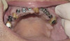
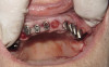
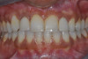
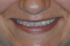
Using a #330 carbide bur, a depth cut to the hilt of the bur was placed buccal–lingually and mesial–distally, creating a cross pattern (Figure 17). On a horizontal plane, the same bur was used to connect the mesial and buccal depth cuts, which resulted in removal of the mesial cusp (Figure 18). The same steps were followed to remove the distal cusp (Figure 19). The lingual cusps were then reduced in the similar fashion (Figure 20). A flat-end diamond bur was then used to remove the decay in the mesial area and the remaining restoration and decay in the distal portion. A #7801 finishing bur was used to break the contact and flatten the mesial margin surface (Figure 21). The last step was to use a finishing bur (#7686) over the entire preparation to smooth any sharp angles and reduce the thickness of the smear layer (Figure 22). The tooth was scanned (Figure 23) and a milled lithium-disilicate restoration was fabricated. The pre-sintered restoration was tried in for fit and to check the occlusion. Surface stains were applied (Figure 24) and the crown was then removed. A spray-on glaze was applied. The crown was secured onto a crystallization pin with object putty and placed in a two-cycle porcelain furnace for final crystallization. Upon cooling, the restoration was bonded into place (Figure 25). In a open-mouth view, the unprepared axial walls of the tooth did not create any visual objection (Figure 26).
Conclusion
The non-retentive, all-ceramic posterior restoration is a viable option in specific situations depending on the location, esthetics, and occlusal habits that may be present. Its advantages include elimination of the axial portion of the traditional crown preparation, which provides for a more conservative approach to restoring posterior teeth. Case selection is vital to the success of the technique. Using the previously described step-by-step preparation technique will ensure proper occlusal reduction, preservation of enamel, and supra-gingival margins where possible, and improve margin definition and decrease the amount of time the preparation bur is in contact with the tooth.
Acknowledgment
The author would like to thank Ruth Egli, RDH, for her editorial contribution.
References
1. Bakeman EM, Kois JC. Posterior, all-porcelain, adhesively retained restorations. Inside Dentistry. 2009;5(5):20-30.
2. Heintze SD, Cavalleri A, Forjanic M, et al. Wear of ceramic and antagonist–a systematic evaluation of influencing factors in vitro. Dent Mater. 2008;24(4):433-49.
3. Kramer N, Kunzelmann KH, Taschner M, et al. Antogonist enamel wears more than ceramic inlays. J Dent Res. 2006;85(12):1097-1100.
4. Koc D, Dogan A, Bek B. Bite force and influential factors on bite force measurements: A literature review. Eur J Dent. 2010;4(2):223-232.
5. Donovan T E. Longevity of the tooth/restoration complex: a review. J Calif Dent Assoc. 2006;34(2):122-128.
6. Trushkowsky RD, Burgess JO. Complex single-tooth restorations. Dent Clin North Am. 2002;46(2):341-365.
7. McLaren EA. Shade analysis and communication: 2010. Inside Dentistry. 2010;6(5):58-66.
8. Fennis WM, Kuijs RH, Kreulen CM, et al. A survey of cusp fractures in a population of general dental practices. Int J Prosthodont. 2002;15(6):559-563.
9. Bader JD, Shugars DA, Martin JA. Risk indicators for posterior tooth fracture. J Am Dent Assoc. 2004;135(7):883-892.
10. Wahl MJ, Schmitt MM, Overton DA, Gordon MK. Prevalence of cusp fractures in teeth restored with amalgam and with resin-based composite. J Am Dent Assoc. 2004;135(8):1127-1132.
11. Agar JR, Weller RN. Occlusal adjustment for initial treatment and prevention of the cracked tooth syndrome. J Prosthet Dent. 1988;60(2):145-147.
12. Abou-Rass M. Crack lines: the precursors of tooth fracture – their diagnosis and treatment. Quintessence Int Dent Dig. 1983;14(4):437-447.
13. Ratcliff S, Becker IM, Quinn L. Type and incidence of cracks in posterior teeth. J Prosthet Dent. 2001;86(2):168-172.
14. Alomari Q, Al-Kanderi B, Qudeimat M, Omar R. Re-treatment decisions for failed posterior restorations among dentists in Kuwait. Eur J Dent. 2010;4(1):41-49.
15. Clausen J-O, Abou Tara MA, Kern M. Dynamic fatique and fracture resistance of non-retentive all-ceramic full-coverage molar restorations. Influence of ceramic material and preparation design. Dent Mater. 2010;26(6):533-538.
16. Malament KA, Socransky SS. Survival of Dicor glass-ceramic dental restorations over 16 years. Part III: effect of luting agent and tooth or tooth-substitute core structure. J Prosthet Dent. 2001;86(5):511-519.
17. Mota CS, Demarco FF, Camacho GB, Powers JM. Tensile bond strength of four resin luting agents bonded to bovine enamel and dentin. J Prosthet Den. 2003;89(6):558-64.
18. Piemjai M, Arksornnukit M. Compressive fracture resistance of porcelain laminates bonded to enamel or dentin with four adhesive systems. J Prosthodont. 2007;16(6):457-464.
19. Dong XD, Darvell BW. Stress distribution and failure mode of dental ceramic structures under Hertzian indentation.Dent Mater. 2003:19(6):542-551.
20. Rekow ED, Harsono M, Janal M, et al. Factorial analysis of variables influencing stress in all-ceramic crowns. Dent Mater. 2006; 22(2):125-132.
21. Krifka S, Stangl M, Wiesbauer S, et al. Influence of different cusp coverage methods for the extension of ceramic inlays on marginal integrity and enamel crack formation in vitro. Clin Oral Investig. 2009;13(3):333-341.
22. Soares CJ, Martins LR, Fonseca RB, et al. Influence of cavity preparation design on fracture resistance of posterior Leucite-reinforced ceramic restorations.J Prosthet Dent. 2006;95(6):421-429.
23. Christensen GJ. Considering tooth-colored inlays and inlays versus crowns. J Am Dent Assoc. 2008;139(5):617-620.
24. Helvey GA. Chairside CAD/CAM: Lithium disilicate restoration for anterior teeth made simple. Inside Dentistr. 2009;5(10):58-67.
25. McLaren EA, White SN. Glass-infiltrated zirconia/alumina-based ceramic for crowns and fixed partial dentures: Clinical and laboratory guidelines. Pract Periodontics Aesthet Dent. 1999;11(8):985-994.
26. Giordano R. Materials for CAD/CAM-produced restorations. J Am Dent Assoc. 2006;137(suppl):14S-21S.
27. Ayad MF. Effects of tooth preparation burs and luting cement types on the marginal fit of extracoronal restorations. J Prosthodont. 2009;18(2):145-151.
28. Burgess JO. Impression material basics. Inside Dentistry. 2005;1(1):30-34.
29. Hirata T, Nakamura T, Wakabayashi K, Yatani H. Study of surface roughness and marginal fit using a newly developed microfinishing bur and preparation technique. Inter J Micro Dent. 2009;1(1):61-64.
30. Yiu CK, Hiraishi N, King NM, Tay FR. Effect of dentinal surface preparation on bond strength of self-etching adhesives.J Adhes Dent. 2008;10(3):173-182.
31. Barros JA, Myaki SI, Nor JE, Peters MC. Effect of bur type and conditioning on the surface and interface of dentine. J Oral Rehabil. 2005;32(11):849-856.
32. Magne P, Kim TH, Cascione D, Donovan TE. Immediate dentin sealing improves bond strength of indirect restorations. J Prosthet Dent. 2005;94(6):511-519.
33. Magne P, Nielsen B. Interactions between impression materials and immediate dentin sealing. J Prosthet Dent. 2009;102(5):298-305.
34. Öztürk AN, İnan Ö, İnan E, Öztürk B. Microtensile bond strength of CAD-CAD and pressed-ceramic inlays to dentin, Eur J Dent. 2007;1(2):91-96.
35. Hooshmand T, Parvizi S, Keshvad A. Effect of acid etching on the biaxial flexural strength of two hot-pressed glass ceramics. J Prosthodont. 2008;17(5):415-419.
36. Mono H, Albou-Daya M. effect of acid etching on the biaxial flexural strength of heatpressed glass ceramic. J Egyptian Dent Assoc. 2000;46:1477.
37. Clelland NL, Warchol N, Kerby RE, et al. Influence of interface surface conditions on indentation failure of simulated bonded ceramic onlays. Dent Mater. 2006;22(2):99-106.
38. Russell DA, Meiers JC. Shear bond strength of resin composite to Dicor treated with 4-META. Int J Prosthodon. 1994;7(1):7-12.
39. Kato H, Matsumura H, Tanaka T, Atsuta M. Bond strength and durability of porcelain bonding systems. J Prosthet Dent. 1996;75(2):163–168.
40. Alex G. Preparing porcelain surfaces for optimal bonding. Functional Esthetics and Restorative Dentistry. 2008;2(1):38-49.
About the Author
Gregg A. Helvey, DDS, Adjunct Associate Professor, Virginia CommonwealthUniversity School of Dentistry, Richmond, Virginia , Private Practice, Middleburg, Virginia