Cone-Beam Computed Tomography: A Clinician’s Perspective
Claudio M. Levato, DDS, FACD; Allan G. Farman, BDS, PhD, MBA, DSc; Douglas L. Chenin, DDS
Technology and computer integration in dentistry has had its challenges and rewards;1,2 and with the passage of time and greater market penetration, challenges and rewards still persist.3,4 The question that continues to surface is why the integration of technology has been so difficult for many dentists to accept.5 In the authors’ opinion, a certain level of infrastructure needs to be in place for technology to deliver synergistic value. For the last several decades clinicians have seen the introduction of numerous applications for dentistry that build on the computer infrastructure that was initiated with practice management software and the gradual introduction of computers into the clinical setting.6 The driving force for bringing computers into the operatory was digital imaging, primarily digital radiology.7
Nearly 20 years have passed since the first intraoral digital sensor was introduced by the French dentist, Francis Mouyen at the First European Congress of Dental and Maxillofacial Radiology in Geneva,8,9 and still there is less than 30% market penetration of this technology in the United States.10 The latest ripple in the world of dental digital imaging, three-dimensional (3D) imaging, appears to be coming at light speed, but in reality, computed tomography (CT) scans have been used widely in medicine for decades. It is with the introduction of maxillofacial cone-beam computed tomography (CBCT) that the dental 3D world is awakening and responding aggressively. A series of articles for Inside Dentistry in January11 and June 200712 and January 200813 are extremely helpful in getting a well-rounded overview of the technology and applications.
While there is abundant information and education on maxillofacial CBCT, unfortunately there is also a plethora of misleading marketing for this technology that can cause a great deal of confusion. This article focuses on helping the nonradiologist dentist get a better handle on how CBCT can provide more accurate and reliable information in the treatment of patients.
History of CT
In 1972, Godfrey Newbold Hounsfield revolutionized diagnostic medicine with the invention of the CT scanner, which gained him the honors of British Knighthood and the Nobel Prize in Medicine in 1979. Hounsfield’s invention showed that it was feasible, based on a very large number of measurements, to reconstruct a cross-sectional slice of a patient with fairly high accuracy, making it possible to visually inspect a patient’s inside anatomy without the need for invasive surgery. In the following years, the CT technique was refined and the image quality of the slices improved dramatically.
While two-dimensional slice-based CT has been in clinical use for many years, the current trend is toward 3D or volumetric CT, in which projection acquisition is geared directly toward a 3D reconstruction of the inspected field of view (FOV). Such 3D representations can be obtained with standard fan-beam (slice-based) CT, in which a number of separately acquired, thin axial slices are simply stacked on top of one another. A very simple analogy for the fan-beam CT would be a sliced loaf of bread stacked together. However, obtaining the whole loaf of bread initially is achievable with volumetric (cone-beam) CT.
One of the earliest 3D volumetric scanners was the Dynamic Spatial Reconstructor (DSR), installed in the Medical Sciences Building on the Mayo Clinic Rochester campus in 1978. As described by Richard Robb,14 14 rotating 2D cameras with 240 scan lines each receive photons of 14 opposing x-ray point sources at a frequency of 1/60 sec. At the time the DSR was developed, 3D reconstruction was still in its infancy and no true 3D reconstruction algorithm was available. In need of pioneering results, the DSR was forced to employ a standard 2D reconstruction algorithm, originally designed to reconstruct cross-sectional slices from fan-beam projection data. In an approach termed the “stack-of-fans” method, the DSR simply treated each axial row of projection data as coming from a rotating virtual 2D fan-beam source, located in the same plane.
The DSR was designed as a noninvasive diagnostic device to detect lung cancer and heart disease in their early stages. It emerged as an answer to the tremendous challenge of using CT to provide 3D reconstruction of moving objects, such as the cyclic motion of the beating heart. Because of its efficacy, it has become the standard in the field of 3D real-time imaging by which other noninvasive imaging modalities are measured in their effectiveness for achieving various diagnoses.
How CBCT Works
CBCT scanners use a 2D detector (Figure 1), which allows for a single rotation of the x-ray source-detector system to generate a scan of the entire region of interest, as compared with conventional CT scanners, where multiple ”slices” must be stacked to obtain a complete image.
In comparison with conventional fan- beam spiral-scan geometries, cone-beam geometry has higher efficiency in x-ray use. Fan-beam scans are obtained by transmission of the FOV by a narrow, fan-shaped beam of x-rays or multiple beams simultaneously. The x-ray beam generated by the tube is collimated to a fan-shaped beam (or collection of beams) by rejecting the photons outside the beam(s), resulting in a relatively inefficient use of the x-ray photons.
The CBCT technique benefits from fast volumetric data acquisition, possible because it requires only a single scan to capture the entire object with a cone of x-rays. Actually, the time required to acquire a single cone-beam projection is comparable with that required by a single fan-beam projection or simultaneous projections with multi-slice systems. Because it takes several fan-beam scans to complete the imaging of a single object, the acquisition time for the fan beam can be much longer if the system does not image sufficient multiple slices simultaneously.
Various technical approaches have been used to reduce the acquisition time of the fan-beam method, such as higher power x-ray tubes and multiple detectors, making the design unsuitable for a compact scanner, and ultimately resulting in significant equipment cost increase.
Moreover, the emitted x-rays that fan out in a conventional fan-beam CT system are still underused because there is only one (or, in the more recent models, a few) linear detector array(s) that receive them. Those x-rays that are not used for image formation unnecessarily contribute to patient dose. The mechanical simplicity and the moderate x-ray requirements make CBCT equipment much more cost-effective than conventional fan-beam CT.15
Image Elements
Most of us are familiar with pixels (picture element), which are unit measurements used in computer screens, digital cameras, and 2D intraoral sensors. With three dimensions, the unit of measurement is a voxel (a blending of the words volumetric and pixel), representing a value on a regular grid in 3D space. With CBCT technology, the voxels are isotropic, meaning that they are equal in all dimensions. This feature is important for implant planning and execution16 because of the 1:1 relationship in CBCT images in all three orthogonal planes. Measurement is generally precise, so standardized data (usually Digital Imaging and Communications in Medicine [DICOM] files) can be exported for use in fabricating stereolithographic surgical guides to assist in the positioning of implant placement.17
CT Scanners
There are currently at least 16 CBCT scanners available in the United States, with more going through the US Food and Drug Administration (FDA) approval process.
All CBCT units provide 3D information; however, each manufacturer approaches the project differently with its choice of patient positioning, scanning parameters, and viewing software. CBCT units most commonly are categorized by their x-ray detection system:18 image-intensifier (II) detector or flat-panel (FP) detector.19 II detectors are an older and less expensive technology, which generally results in more noise than FP detectors, and they need to be preprocessed to reduce geometric distortions inherent in the detector configuration.20 The radiation beam is 3D in shape and similar to the photon energy used in digital or conventional dental radiology. The receptor captures 2D images either directly with the FP, which absorbs the photons that are converted to an electric charge which is measured by the computer, or with the II, which captures the photons and converts them to electrons that contact a fluorescent screen that emits light captured by a charged-coupled device (CCD) camera. The software then reconstructs the sum of exposures with the manufacturer’s proprietary algorithms into as many as 512 axial slice images.21
DICOM format images are standard for handling, storing, printing, and transmitting information in medical imaging, including those from CBCT.22 In 3D imaging this becomes a great asset in exporting this data set to third-party software programs that will facilitate image renderings, implant planning programs, and making surgical guides to assist in implant placement.
Many CBCT units have a variable FOV that allows the clinician to limit the radiation exposure to the region of interest. The limiting factor is the size of the image detector, which varies depending on the manufacturer, but for the sake of simplicity, this article will discuss them in categories—small (< 6 in), medium (6 in), large (9 in), and extra-large (12 in) FOVs (Figure 2 and Figure 3). The maximum image of a small FOV usually can accommodate several teeth or a sextant of an arch. The maximum medium FOV can accommodate the normal adult dentition, and the maximum large FOV encompasses the maxillofacial anatomy including the condyles and most of the orbits. Finally, the extra-large FOV can accommodate the full skull in most cases. Regardless of the volume capacity of the unit, it is important to restrict the FOV to the region of interest, which has a significant effect on the amount of radiation absorbed.23
Larger FOV units can be collimated to a specific region of interest, thus reducing exposure and size of the image. Small FOV units require multiple scans to expand the region of interest, increasing radiation and complicating the process of integrating the data. If the small FOV unit uses a DICOM format, the data can be exported to a third party software program, such as InVivoDental™ (Anatomage Inc, San Jose, CA), which can stitch together separate scans of the patient to show a single image (Figure 4). This same software can be used for intricate segmentation of different tissues.
Applications for CBCT
There are numerous applications for CBCT in dentistry because this technology far surpasses film or 2D digital radiology in giving diagnostic information of the dental or maxillofacial regions. The amount of information one can obtain from a 3D image over a 2D image is considerable. However, the diagnosis comes from the assessment of clinical and imaging evaluation, and the clinician must be ever mindful of the risks vs benefits to the patient in the use of radiation, regardless of the amount. Use guidelines always must be in line with the “As Low As Reasonably Achievable” (ALARA) principle,24 and if a definitive diagnosis can be made with a single intraoral radiograph, there is no justification for using CBCT. Some CBCT applications that have been reported in the literature include:
- Dental implants17,25,26
- Impactions27-29
- Inferior alveolar nerve location30,31
- Airway studies for sleep apnea32
- Temporomandibular joint (TMJ) structure visualization33
- Orthodontics34
- Periodontics35
- Endodontics36
Advantages of CBCT
CBCT will not replace intraoral radiology for general dental applications; it will complement it for indications that require more information. It also will reduce the need for conventional CT scans for dental issues because of its significant advantages11,18,21:
- X-ray beam limitation
- Image accuracy
- Rapid scan time
- Dramatic dose reduction
- Display modes for volume rendering
- Reduced image artifacts
- Oblique planar reformation
- Curved planar reformation
- Serial transplanar reformation
- Multiplanar volume reformations
All these features truly make this a phenomenal instrument to advance the clinical applications for dentistry. As with all technology, CBCT has limitations. The patient must be motionless during the scanning to achieve a good image; otherwise the image may display streaking. There also will be artifacts in the image around metal prostheses, making it difficult to evaluate teeth with metal restorations. Furthermore, the larger FOV systems can image tissues with which the dentist is not familiar, but might be held responsible for interpreting. It is often prudent to refer such image volumes for evaluation by a specialist in oral and maxillofacial radiology. Another caution is that professional judgment is needed to place surgical stents appropriately and to understand that such guides do have a margin for error.
CBCT Images
Because CBCT is an imaging application, this article illustrates some of the applications with selected images from different manufacturers to demonstrate the far-reaching effect this technology can have on the dental profession.
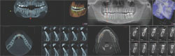
It is important to note that the various CBCT units come with standard viewing software, which will allow the dentist to examine the selected area of interest in all three planes: axial, coronal, and sagittal (Figure 5).
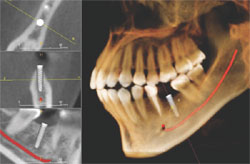
Basic enhancements include zoom or magnification and visual adjustments to narrow the range of the displayed gray scale and contrast levels within the window, as well as cursor-driven measurements and annotations. Third party software programs will provide enhancement features that will allow the image to render with color, highlighting greater detail to the volume. These programs usually have additional functions, such as mandibular nerve location and implant planning (Figure 6).
As with any technology, use of CBCT imaging requires a learning curve that may include education to a higher level of competency in anatomy and radiographic interpretation if reading the images is planned. The American Academy of Oral and Maxillofacial Radiology has stated that CT and implant imaging should be performed only by a board-certified oral and maxillofacial radiologist or a dentist with adequate training or experience.37 In most states, there are oral and maxillofacial radiologists willing to provide the service of reading the image volume and sending the general dentist a report. The authors strongly recommend this service with any volume that shows anatomy other than dentition. The time saved by using such a service allows the dentist to concentrate on clinical dentistry.
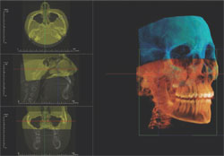
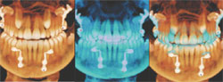
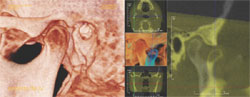
For situations such as orthognathic surgery, separate CBCT scans made at intervals during therapy can be superimposed to visually demonstrate clinical progress (Figure 7). CBCT for orthodontics, while widely adopted in California, still awaits evidence that it improves clinical outcomes. TMJ visualization can be facilitated with CBCT and 3D rendering (Figure 8); image quality can be exceptional.
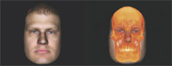
With 3D image data sets, small FOV images can be stitched together or two separate images can be superimposed to show a pre- and postoperative condition or simply a change in position, such as an open and closed TMJ view. It is also possible to take a conventional 2D digital photograph and identify enough points of reference with the 3D CBCT data set that the photograph can be superimposed over the bony structures to place the face of the patient over his or her hard tissues (Figure 9).
Conclusion
The references to clinical and scientific resources in this communication are aimed at being a baseline for ongoing education in this new and exciting technology. Cost has been a significant limiting factor. Before the 2008 Chicago Midwinter Meeting, most available CBCT units were in the $200,000 to $300,000 range. However, at the meeting, a number of newer CBCT models were launched for the dental community.
The first FDA-approved CBCT, in 2001, was the NewTom™ 9000 (AFP Imaging/QR, Verona, Italy), followed by the NewTom™ 3G, and at the American Dental Association 2007 Annual Congress in San Francisco, the manufacturer unveiled its latest generation—NewTom™ VG. The newer generation has better resolution, decreased radiation, and ease of function, all at a lower cost. Figure 10 shows comparative images from the original to the latest model.
At the 2008 Chicago Midwinter Meeting, KaVo Dental Corp/Gendex Dental Systems (Lake Zurich, IL) introduced the GX CB 500™ for a meeting price of $119,000. This unit is a reduced FOV version of the i-CAT® (Imaging Sciences International, Hatfield, PA). The i-CAT uses a standard 17-cm diameter by 13-cm height with an extended view capability of 16-cm diameter by 23-cm height. The GX CB 500 has a standard scan of 8 cm by 8 cm and an extended diameter of 8-cm height by 14-cm diameter to show the mandibular condyles.
At the same meeting, Kodak Dental Systems (Rochester, NY) introduced its 9000C 3D Extraoral Imaging System in the US market for a price of $108,000. This system combines a digital panoramic unit with a very reduced FOV 3D complementary metal-oxide semiconductor (CMOS) imaging system. The scan size is smaller than the medium FOV and can image a sextant of teeth. This system has remarkably high spatial resolution with isotropic voxel dimensions of 0.076 mm, and will be useful for endodontics.
With costs for 3D digital imaging technologies ranging from $100,000 to $300,000, general dental clinicians must differentiate between the 16 or more units available to determine if this technology should be incorporated into their practice. For smaller FOV systems, several combined digital 2D and 3D systems now are available. Planmeca USA Inc (Roselle, IL) first introduced a small FOV (8 cm by 8 cm) unit that can be upgraded to its ProMax 3D digital panoramic unit as a separate replaceable FP detector that is interchangeable with the panoramic digital sensor detector. In contrast, the new Kodak 9000C 3D has both the 2D and 3D components permanently mounted on the unit, and the dentist can select which application to use by simply rotating the sensors. E-Woo Technology USA Inc (Houston, TX) introduced their Picasso Trio, a digital panoramic, cephalometric, and 3D image detector. The Scanora® 3D (Soredex USA, Milwaukee, WI) recently achieved FDA approval for a combined CBCT medium FOV system that combines panoramic radiology capabilities.
The party is not complete without mentioning the other systems that have been around for a few years. J. Morita USA Inc (Irvine, CA) offers the 3D Accu- i-tomo 80, Imtec Corp (Ardmore, OK) offers the ILUMA™, Sirona USA LLC (Charlotte, NC) offers the Galileos, and Hitachi Medical Systems America, Inc (Twinsburg, OH) offers the CB MercuRay™. The Alphard 3030 (Asahi Roentgen Ind Co, Ltd, Kyoto, Japan) and the MyRay SkyView (Cefla Dental Group, Imola, Italy) also recently have been FDA- approved for sale in the United States.
No matter how exciting a new technology is, the dentist still has to look at its use in his or her practice as a business decision. There has to be a return on investment, and if this technology truly improves the ability to better care for patients, its incorporation should yield a return. For multispecialty group practices or group surgical specialists, it makes a great deal of sense to incorporate the technology at this time, either in-office or by referral to an imaging center. For general practices that are invested heavily in implant placement or complex reconstructive dentistry, there is great value in expediting more definitive care. However, for most general practitioners, it would be a significant financial investment that may not deliver a return. For these clinicians, there are thousands of units sold already, and all that is needed is access to one for the more complex cases or for implant placement. Everyone should be able to refer patients for a CBCT when necessary or desired, without having to own a system. The standard of care, especially for implants, is moving rapidly toward CBCT, and rightfully so.
References
1. Levato CM. Integrating computers: a front line perspective. Dent Today. 1997;16(4): 124-127.2. Levato CM. How to profit from computers. Intangible benefits of climbing new peaks. Dent Econ. 1998;88(8):90-94.
3. Levato CM. New technologies: their implementation and the future. Alpha Omegan. 2001;94(4):20-23.
4. Levato CM. Technology integration: a journey, not a destination. Compend Contin Educ Dent. 2002;23(10 Suppl 2):4-10.
5. Levato CM. Putting technology in place successfully. J Am Dent Assoc. 2004;135(Suppl): 30S-37S.
6. Schleyer TK.Why integration is key for dental office technology. J Am Dent Assoc. 2004; 135(Suppl):4S-9S.
7. Farman AG, Levato CM, Gane D, et al. In practice: how going digital will affect the dental office. J Am Dent Assoc. 2008; 139(Suppl): 14S-19S
8. Mouyen F, Benz C, Sonnabend E, et al. Presentation and physical evaluation of RadioVisioGraphy. Oral Surg Oral Med Oral Pathol. 1989;68(2): 238-242.
9. Wenzel A. Two decades of computerized information technologies in dental radiography. J Dent Res. 2002;81(9):590-593.
10. Brian JN, Williamson GF. Digital radiography in dentistry: a survey of Indiana dentists. Dentomaxillofac Radiol. 2007;36(1):18-23.
11. Farman AG, Levato CM, Scarfe WC. A primer on cone beam CT. Inside Dentistry. 2007;3(1):90-93.
12. Farman AG, Levato CM, Scarfe WC. 3-D X-Ray: An Update. Inside Dentistry. 2007; 3(6):70-74.
13. Farman AG, Levato CM, Scafe WC, et al. Education in the round: multidimensional imaging in dentistry. Inside Dentistry. 2008;4(1):2-4.
14. Robb RA. Dynamic spatial reconstructor: an x-ray video fluoroscopic CT scanner for dynamic volume imaging of moving organs. IEEE Trans Med Imaging. 1982;1(1):22-23.
15. Pasini A, Casali F, Bianconi D, Rossi A, Bontempi M. A new cone beam computed tomography system for dental applications with innovative 3D software. Int J CARS. 2007;1(5):1265-1273.
16. Hatcher C, Dial C, Mayorga C. Cone beam CT for pre-surgical assessment of implant sites. J Calif Dent Assoc. 2003;31(11): 825-833.
17. Sarment DP, Sukovic P, Clinthorne N. Accuracy of implant placement with a stereolithographic surgical guide. Int J Oral Maxillofac Implants. 2003;18(4):571?577.
18. Scarfe WC, Farman AG, Sukovic P. Clinical applications of cone-beam computed tomography in dental practice. J Can Dent Assoc. 2006;72(1):75-80.
19. Baba R, Konno Y, Ueda K, et al. Comparison of flat-panel detector and image-intensifier detector for cone-beam CT. Comput Med Imaging Graphic. 2002;26(3):153-158.
20. Baba R, Ueda K, Okabe M. Using a flap-panel detector in high resolution cone beam CT for dental imaging. Dentomaxillofac Radiol. 2004;33(5): 285-290.
21. Howerton WB Jr, Mora MA. Advancements in digital imaging; what is new and on the horizon. J Am Dent Assoc. 2008;139(Suppl): 20S-24S.
22. Farman AG. Raising standards: digital interoperability and DICOM. Oral Surg Oral Med Oral Pathol Oral Radiol Endod. 2005;99(5): 525-526.
23. Ludlow JB, Davies-Ludlow LE, Brooks SL, et al. Dosimetry of 3 CBCT devices for oral and maxillofacial radiology: CB Mercuray, NewTom 3G and i-CAT [published erratum in: Dentomaxillofac Radiol. 2006 Sep;35(5): 392]. Dentomaxillofac Radiol. 2006;35(4): 219-226.
24. Farman AG. ALARA still applies. Oral Surg Oral Med Oral Pathol Oral Radiol Endod. 2005;100(4):395-397.
25. Aranyarachkul P, Caruso J, Gantes B, et al. Bone density assessments of dental implant sites: 2. Quantitative cone-beam computerized tomography. Int J Oral Maxillofac Implants. 2005;20(3):416-424.
26. Sato S, Arai Y, Shinoda K, et al. Clinical application of a new cone-beam computerized tomography system to assess multiple two-dimensional images for the preoperative treatment planning of maxillary implants: case reports. Quintessence Int. 2004;35(7): 525-528.
27. Pawlzik J, Cohen M, Willers R, et al. A comparison of conventional panoramic radiographs with volumetric computed tomography in the preoperative assessment of impacted mandibular third molars. J Oral Maxillofac Surg. 2002;60(9):979-984.
28. Mah J, Enciso R, Jorgensen M. Management of impacted cuspids using 3-D volumetric imaging. J Calif Dent Assoc. 2003; 31(11):835-841.
29. Danforth R, Peck J, Hall P. Cone beam volume tomography: an imaging option for diagnosis of complex mandibular third molar anatomical relationships. J Calif Dent Assoc. 2003;31(11): 847-852.
30. Worthington P. Injury to the inferior alveolar nerve during implant placement: a formula for protection of the patient and clinician. Int J Oral Maxillofac Implants. 2004;19(5): 731-734.
31. Erickson M, Caruso J, Leggitt L. Newtom QR-DVT 9000 imaging used to confirm a clinical diagnosis of iatrogenic mandibular nerve paresthesia. J Calif Dent Assoc. 2003;31(11):843-845.
32. Aboudara C, Hatcher D, Nielson IL, et al. A three-dimensional evaluation of the upper airway in adolescents. Orthodont Craniofac Res. 2003;6(Suppl 1):173-175.
33. Honda K, Matumoto K, Kashima M, et al. Single air contrast arthrography for temporomandibular joint disorder using limited cone beam computed tomography for dental use. Dentomaxillofac Radiol. 2004;33(4): 271-273.
34. Maki K, Inou N, Takanishi A, et al. Computer-assisted simulations in orthodontic diagnosis and the application of a new cone beam x-ray computed tomography. Orthod Craniofac Res. 2003;6(Suppl 1):95-101.
35. Mengel R, Candir M, Shiratori K, et al. Digital volume tomography in the diagnosis of periodontal defects: an in vitro study on native pig and human mandibles. J Periodontol. 2005;76(5): 665-673.
36. Cotton T, Geisler T, Holden D, et al. Endodontic applications of cone-beam volumetric tomography. J Endod. 2007;33(9): 1121-1132.
37. American Academy of Oral and Maxillofacial Radiology, ad hoc Committee on Parameters of Care. Parameters of radiologic care: an official report of the American Academy of Oral and Maxillofacial Radiology. Oral Surg Oral Med Oral Pathol Oral Radiol Endod. 2001;91(5):498-511.
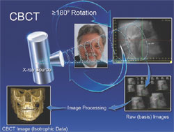 | 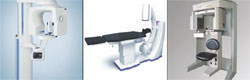 | |||
| Figure 1 How CBCT works: The large arrows represent the path of the x-ray source and detector around the patient. The smaller arrows represent the subsequent flow of image data and reconstruction of the eventual image for display. | Figure 2 Examples of CBCT formats (left to right): ProMax 3D (Small FOV, FP detector, Standing), MyRay SkyView 3D (Medium FOV, II detector, Supine), i- CAT (Large FOV, FP detector, Seated). | |||
 |  | |||
| Figure 3 Comparison of 6-in FOV and 9-in FOV multiview screens (pictured on MyRay SkyView 3D). | Figure 4 Stitching two CBCT data sets using InVivoDental third-party software. Images are imported DICOM files. | |||
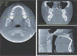 |  | |||
| Figure 5 Representative standard CBCT orthogonal plane slices without enhancement (pictured on i-CAT). | Figure 6 3D data enhancement and implant planning software (pictured on InVivoDental). | |||
 |  | |||
| Figure 7 3D data enhancement and implant planning software (pictured on InVivoDental). | Figure 8 TMJ rendering (left) and superimposition of open and closed TMJ scans (right) (pictured on InVivoDental). | |||
 | ||||
| Figure 9 Superimposition of conventional digital photograph over CBCT scan (pictured on InVivoDental). | Figure 10 Images from NewTom 9000: 2001 (left) and NewTom VG: 2007 (right). | |||
| About the Authors | ||||
| ||||
| ||||
| ||||