3D Digital Scanners: A High-Tech Approach to More Accurate Dental Impressions
Nathan S. Birnbaum, DDS, CAGS(Prosth); Heidi B. Aaronson, DMD; Chris Stevens, DDS; Bob Cohen, CDT
Ever since the introduction of the first digital scanner for making dental impressions in the 1980s, development engineers at a number of companies have enhanced the technologies and created in-office scanners that are increasingly user-friendly and produce precisely fitting dental restorations. These systems are capable of capturing three-dimensional (3D) virtual images of tooth preparations from which restorations may be directly fabricated (CAD/CAM systems) or can be used to create accurate master models for the restorations in a dental laboratory (dedicated impression scanning systems). The use of these products presents a paradigm shift in the way dental impressions are made. Several of the leading 3D dental digital scanning systems are presented and discussed in this article.
A Paradigm Shift in the Concept for Making Dental Impressions
The acquisition of an accurate negative copy of a prepared tooth or teeth and of the adjacent and opposing teeth and the establishment of a correct interocclusal relationship, as well as the conversion of this information into precise replicas of the dentition on which indirect restorations can be made, are the ultimate goals of the impression process in restorative dentistry.
The widely used techniques currently employed for obtaining elastomeric impressions and for creating gypsum models from those impressions have only been in use since 1937, when Sears introduced agar as an impression material for crown preparations.1 The first elastomeric material specifically produced for the purpose of dental impression-making was Impregum™, a polyether material introduced by ESPE, GmbH in 1965.
Many dentists are reluctant to become involved with newer technologies in impression making because they either mistakenly believe that the elastomeric technique and materials have been around since time immemorial and are immutable, or that 3D digital scanners are too new a technology that is not yet “ready for prime time.” In fact, elastomeric impression materials, with their many inherent problems,2,3 have only been in use in dentistry for 72 years.
3D digital dental impression scanning systems actually were introduced to the profession in the mid-1980s and have advanced to the degree that, at a meeting of the New England Academy of Cosmetic Dentistry held in Boston in October 2007, master dental technician Lee Culp predicted that most dentists would be using digital scanners for impression making “within 5 years.”
The computer-aided design/computer-aided manufacture (CAD/CAM) dental systems that are currently available are able to feed data obtained from accurate digital scans of teeth directly into milling systems capable of carving restorations out of ceramic or composite resin blocks without the need for a physical replica of the prepared, adjacent, and opposing teeth.
With the development of newer high-strength and esthetic ceramic restorative materials, such as zirconia, laboratory techniques have been developed in which master models poured from elastic impressions are digitally scanned to create stereolithic models on which the restorations are made. Even with such high-tech improvements, it is evident that such second-generation models will not be as accurate as stereolithic models made directly from data obtained from 3D digital scans of the teeth and provided by dedicated 3D scanners designed for impression making.
This article outlines the features of two CAD/CAM systems and two dedicated 3D impression digital scanners that have been gaining in popularity in this emergent field of technology.
CAD/CAM Systems
CAD/CAM technology has been in use for a half century. It originated in the 1950s with numerically controlled machines feeding numbers on paper tape into controllers wired to motors positioning work on machine tools. It advanced in the 1960s with the creation of early computer software that enabled the design of products in the aircraft and automotive industries.
The introduction of CAD/CAM concepts into dental applications was the brainchild of Dr. Francois Duret in his thesis written at the Université Claude Bernard, Faculté d’Odontologie, in Lyon, France in 1973, entitled “Empreinte Optique” (Optical Impression). He developed a CAD/CAM device, obtained a patent for it in 1984,4 and brought it to the Chicago Midwinter Meeting in 1989. There, he fabricated a crown in 4 hours as attendees watched.
In the meantime, in 1980, a Swiss dentist, Dr. Werner Mörmann and an electrical engineer, Marco Brandestini, developed the concept for what was to be introduced in 1987 by Sirona Dental Systems LLC (Charlotte, NC) as the first commercially viable CAD/CAM system for the fabrication of dental restorations—CEREC®.
CEREC® AC
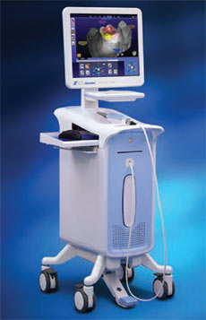
The CEREC® system (Figure 1), an acronym for Chairside Economical Restoration of Esthetic Ceramics, was a bold effort to combine a 3D digital scanner with a milling unit to create dental restorations from commercially available blocks of ceramic material in a single appointment. Since its introduction in 1987 by Sirona Dental Systems LLC as the first commercially viable CAD/CAM system designed exclusively for the fabrication of ceramic inlays and onlays, CEREC® has undergone a series of technological improvements, culminating in the CEREC AC® powered by BlueCam®, launched in January 2009. The later versions of the CEREC® system are capable of producing not only inlays and onlays, but also crowns, laminate veneers, and even bridges.
The CEREC® system uses computer-assisted technologies, including 3D digitization, the storage of the data as a digital model, and proprietary CEREC 3D® software that proposes a restoration shape based on biogeneric comparisons to adjacent and opposing teeth, which enables the dentist to modify the design of the restoration. After this is accomplished, the data is transmitted to a milling machine, the latest version of which, CEREC inLab® MC XL, is capable of milling a crown in as little as 4 minutes from a block of ceramic or composite material.
Whereas the earlier versions of CEREC® employed an acquisition camera that depended on an infrared laser light source, advancements in the performance of blue light-emitting diodes (LEDs) in parameters that are relevant for 3D acquisition cameras have now surpassed the quality of the longer-wavelength infrared light source. The shorter-wavelength intense blue light projected by the blue LEDs allows for greater precision of the resultant optical image.
The camera projects a changing pattern of blue light onto the object (Figure 2) and then reads it back at a slightly different angle, referred to as “active triangulation technique.” It uses a telecentric beam, which permits the capture of essential information from all of the prepared tooth’s surfaces in a single view.
With this system, the impression process necessitates achieving adequate visualization of the margins of the tooth preparation by proper tissue retraction or troughing and hemostasis. This is true not only for digital scanning, but also for conventional elastomeric impressions. The entire area being impressed needs to be coated completely with a layer of biocompatible titanium dioxide powder to enable the camera to register all of the tissues.
Several image views are then made from an occlusal orientation ensuring capture of the tooth or teeth being restored, as well as of the adjacent and opposing teeth. Next, the preparation is shown on the monitor (Figure 3) that enables the dentist to view the prepared tooth from every angle and to focus on magnified areas of the preparation. The “die” is “cut” on the virtual model, and the finish line is delineated by the dentist directly on the image of the die on the monitor screen.
Then, the CAD biogeneric proposal of an idealized restoration is presented by the system, and the dentist is given the opportunity to make adjustments to the proposed design using a number of simple and intuitive on-screen tools.
Once the dentist is satisfied with the proposed restoration, he or she mounts a block of homogeneous ceramic or composite material of the desired shade in the milling unit and proceeds with fabrication of the physical restoration. The use of color- coded tools during the design stage of the process to determine the degree of interproximal contact helps to ensure finished restorations that require minimal, if any, adjustments before cementation.
With the recent introduction of the CEREC AC® system, the dentist has the choice of capturing digital impressions of the teeth and fabricating an indirect dental restoration in-house in a single visit, or of forwarding the data using CEREC Connect® directly to the dental laboratory which, in turn, can choose to create the restoration virtually and mill the restoration in the laboratory, or even to have accurate hard resin models made from the data and then manufacture the restoration on the physical models.
E4D Dentist
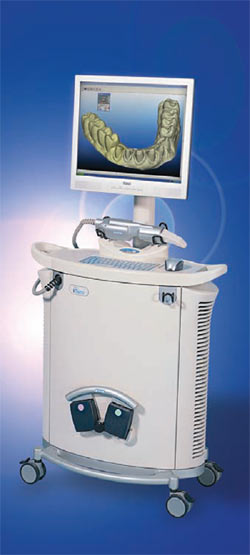
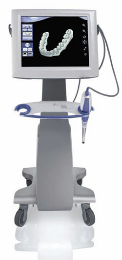
The E4D Dentist system, introduced by D4D Technologies LLC (Richardson, TX) in early 2008, consists of a cart containing the design center (computer and monitor) and laser scanner (Figure 4), a separate milling unit, and a job server and router for communication. The scanner, termed the IntraOral Digitizer, has a shorter vertical profile than that of the CEREC, so the patient is not required to open as wide for posterior scans.
The E4D does not require the use of a reflective agent (powder) to enable the capture of fine detail on the target site in most cases. Therefore, once proper retraction and hemostasis have been obtained, scanning begins by simply placing the IntraOral Digitizer directly above the prepared tooth. The scanner must be held a specific distance from the surface being scanned—this is achieved with the help of rubber-tipped “boots” that extend from the head of the scanner. Placing these rests on adjacent teeth steadies the scanner at this optimal distance.
The user holds down the foot pedal while centering the image. Once the desired area is centered on the on-screen bullseye, the pedal is released and the image is captured (Figure 5). The ICEverything™ feature of the E4D takes actual pictures of the teeth and gingiva. A diagram on the monitor shows the user how to orient the scanner to obtain the next image. As successive pictures are taken, they are wrapped around the 3D model to create the ICEverything model. This 3D ICE view makes margin detection simpler to achieve. The touch screen monitor enables the dentist to view the preparation from various angles to ensure its accuracy.
It is not necessary to scan the opposing arch. Instead, an occlusal registration is created with impression material, trimmed, and then placed on top of the prepared tooth. The scanner captures a combination of the registration material and the neighboring teeth that are not covered by the material. This data is used to design restorations with proper occlusal heights.
The design system of the E4D is then capable of autodetecting and marking the finish line on the preparation. Once this landmark is approved by the dentist, the computer uses its Autogenesis™ feature to propose a restoration (Figure 6), chosen from its anatomical libraries, for the tooth being worked on. As with the CEREC® system, the operator is provided with a number of highly intuitive tools to modify the restoration proposal.
Once the final restoration is approved, the design center transmits the data to the milling machine. Using blocks of ceramic or composite mounted in the milling machine, and with the aid of rotary diamond instruments which are capable of replacing themselves when worn or damaged, the dentist is able to fabricate the completed restoration.
Dedicated Impression Scanners
Dedicated 3D digital dental impression scanners eliminate several time-consuming steps in the dental office, including tray selection, dispensing and setting of materials, disinfection, and shipment of impressions to the laboratory. In addition, the laboratory saves time by not having to pour base and pin models, cut and trim dies, or articulate casts.
With these systems, the final restorations are produced in the laboratory, but they are fabricated on models created from the data in the digital scans, as opposed to gypsum models made from physical impressions. Patient comfort, treatment acceptance, and education are added benefits. Digital scans can be stored on computer hard drives indefinitely, whereas conventional models, which may chip or break, must be stored physically, which often requires extra space in the dental office.
iTero
In early 2007, the Cadent iTero (Cadent, Carlstadt, NJ) digital impression system (Figure 7) came into the market. The iTero system uses parallel confocal imaging to quickly capture the digital impression. Parallel confocal imaging uses laser and optical scanning to digitally capture the surface and contours of the tooth and gum structure. The Cadent iTero scanner captures 100,000 points of red laser light and has perfect focus images of more than 300 focal depths of the tooth structure. All of these focal depth images are spaced approximately 50 µm apart.
Parallel confocal scanning with the iTero system captures all structures and materials found in the mouth without the need for scanning powders that coat the teeth.
While the ability of the iTero camera to scan without the need for powdering may be advantageous, it necessitates the inclusion of a color wheel into the acquisition unit itself, resulting in a camera with a larger scanner head than the other systems being discussed in this article (Figure 8).
The electronic laboratory script is complete with patient information, delivery date, restoration type, material choice, shade requirements, and any other information particular to the case. The laboratory script initiates the scan process and the visual as well as audible prompts that guide the clinician throughout the digital impression.
Once the teeth have been prepared, capturing the digital impression follows a consistent series of steps for every impression. Soft tissue management, retraction, moisture control, and hemostasis are essential in capturing digital data. Once tissue management has been confirmed, the operator is guided through a consistent series of scanning steps (Figure 9). This will include five scans of the prepared area: occlusal, lingual, buccal, and interproximal contacts of the adjacent teeth. Once these scans are obtained, buccal and lingual 45°-angle views of the remaining teeth in the quadrant or arch and opposing arch are obtained.
When these scans (at least 21) are complete, the patient is asked to close into centric occlusion and a virtual registration is scanned. Overall, complete upper and lower quadrant scans and the virtual bite registration can take less than 3 minutes time, which is less than conventional impressions and bite registration.
Once the digital impression has been completed, the clinician can select from a series of diagnostic tools to evaluate the preparation and complete the impression. The occlusal reduction tool shows in vivid color how much clearance has been created in the preparation for the restoration selected by the clinician. A margin line tool is available to assist in viewing the clearly defined margin. Once the clinician has completely evaluated all aspects of the digital impression, adjustments, if any, are made at that time and a few additional scans will register the changes that were made to the prepared tooth.5
The completed digital impression is sent via a HIPAA-compliant wireless system to the Cadent facility and the dental laboratory. Upon review by the laboratory, the digital file is outputted to a model by Cadent. The model is milled from a proprietary blended resin and is pinned, trimmed, and articulated based on the digital impression created by the clinician. Cadent uses industrial 5-axis milling machines to ensure the precision of the milled models and dies.
Cadent models are unique in that one model is used for both the working model and the soft tissue model. By producing the ditching of the dies virtually, the dies and model are precisely created and eliminate the inaccuracies of hand trimming. The final restoration is then fabricated at the laboratory as specified by the digital prescription.6
Lava Chairside Oral Scanner (C.O.S.)
The Lava™ Chairside Oral Scanner (C.O.S.) was created at Brontes Technologies in Lexington, Massachusetts, and was acquired by 3M ESPE (St. Paul, MN) in October 2006. The product was officially launched in February 2008.
The Lava C.O.S. system (Figure 10) consists of a mobile cart containing a CPU, a touch screen display, and a scanning wand, which has a 13.2-mm wide tip and weighs 14 ounces (Figure 11). The camera at the tip of the wand contains 192 LEDs and 22 lens systems.
The method used for capturing 3D impressions involves Active Wavefront Sampling. The Lava C.O.S. concept of “3D in Motion” incorporates revolutionary optical design, image processing algorithms, and real-time model reconstruction to capture 3D data in a video sequence and model the data in real time. The scanning wand contains a complex optical system comprised of multiple lenses and blue LED cells. Thus, the Lava C.O.S. is able to capture approximately 20 3D data sets per second, or close to 2,400 data sets per arch, for an accurate and high-speed scan.
After the preparation of the tooth and gingival retraction, the entire arch is dried and lightly dusted with powder. The Lava C.O.S. only requires enough powdering to allow the scanner to locate reference points, not heavy powdering as with the CEREC. During the scan, a pulsating blue light emanates from the wand head as an on-screen image of the teeth appears instantaneously.
The dentist guides the wand over the occlusal surfaces, rotates the wand so that the buccal surfaces are scanned, then rotates again to capture the lingual surfaces. The “stripe scanning” is completed once the dentist returns to scanning the occlusal of the starting tooth.
After scanning the tooth preparation, the dentist is able to rotate and magnify the view on the screen, and can also switch from the 3D image to a 2D view of the exact images captured by the camera during the scan (Figure 12). A third option allows the dentist to view these images while wearing 3D glasses.
Once the dentist confirms that all of the necessary details were captured on the scan of the preparation, a quick scan of the rest of the arch is obtained. If there are holes in the scan in areas where data is critical, the dentist simply scans that specific area and the software patches the hole.
The patient is then instructed to close into the maximum intercuspal position (MIP), the buccal surfaces on one side of the mouth are powdered, and a scan of the occluding teeth is captured. The maxillary and mandibular scans are then digitally articulated on the screen.
When all of the scans have been reviewed for accuracy, the dentist fills out an on-screen laboratory prescription. The data is wirelessly sent to the laboratory technician, who then uses customized software to digitally cut the die and mark the margin. 3M ESPE receives the digital file where it is virtually ditched, and the data is seamlessly articulated with the operative, opposing, and bite scans.
At the model manufacturing facility, a stereolithography (SLA) model is generated and sent to the laboratory. Despite the name of the system, it is not dedicated only to the creation of Lava crowns and bridges, as all types of finish lines may be reproduced on the SLA dies, allowing for any type of crown to be manufactured by the dental laboratory.
Digital Impressions: The Laboratory Perspective
Historically, the dental laboratory technician has performed most processes by hand. Over the last decade, dental laboratories have moved rapidly into digital forms of manufacturing. In fact, the growth of digital manufacturing processes is exponential. Today, the laboratory marketplace is teeming with many forms of digital processing. Some of these digital processes include digital scanning, computer aided design (CAD), computer aided milling (CAM), rapid manufacturing (RM), and laser sintering.
The basis for all digital laboratory manufacturing processes is the creation of a digital file for each patient’s unique dental anatomy. Through the use of intraoral scanners, we now have the potential to acquire a digital file directly from a patient’s mouth. This results in improved accuracy of both the dental model and the final prosthesis.
When fabricating prostheses through the use of an intraoral digital scanner, the dental laboratory technician ditches die(s) virtually, with the aid of margin-defining software. This eliminates pick-ups, sterilization procedures, all conventional model and die processing, articulations, related equipment, staff, and inventory. Furthermore, this dramatically increases the level of communication between the technician and dentist.
The technician can quickly e-mail large images of patient’s preparations (3D, 2D, and cross-section) to the dentist, requesting advice as to the virtual trimming of dies. Once the dies have been ditched, the models will be fabricated using rapid manufacturing (Lava C.O.S.), or CAM (iTero).
Because of the remarkable technology of a digital impression, the dentist receives instantaneous computer feedback that is significantly larger than life. As a result, the dentist has the ability to review his or her work prior to submitting it to the laboratory. Being able to do this provides the dentist with the opportunity to correct a poor impression and/or preparation at this first impression appointment. This, in turn, reduces the potential for either compromised work or wasted additional patient appointments.
The digital impression has been shown to provide superior impressions and preparations resulting in improved restoration quality. Dental technicians who have gained experience with digital impressions have seen the quality of work performed by the dentists using this technology improve dramatically.
In the laboratory, the dental technician has the option to fabricate the prostheses through either conventional methods or digital solutions, or a combination of the two. When manufacturing on a digital platform, the exacting nature and related processing of digital information enables simultaneous manufacturing of prosthetic parts. As a result, this will enable the reduction of the manufacturing time cycles. For instance, a patient is scanned with the Lava C.O.S. and models and dies are processed by a centrally located manufacturing facility. Simultaneously, the dental laboratory has access to the same intraoral digital file and can build a CAD/CAM framework, final restoration, and/or a full-contour wax-up using an anatomical library for consistent design.
The quantitative nature of digital systems enables much more consistent process control. For example, design rules in software can quantitatively ensure that bridge connectors meet minimum thickness requirements for the material of choice. In addition, model manufacturing accuracy is validated using coordinate measurement systems and statistical process control.
Perhaps the greatest advantage for both the dental technician and the dentist in going digital is the elimination of many chemical-based processes. By virtue of the elimination of these processes, the accumulation of errors within the treatment and manufacturing cycle is no longer a factor. Some of these processes are: setting of impression materials, setting of die stone and stone base material, setting of casting and pressing investments, and shrinkage of conventional feldspathic ceramic materials.
By eliminating the process of conventional impressions, we no longer are concerned with the possibility of error due to air bubbles, tearing of impression material, drag, tray movement, tray deflection, too little impression material, inadequate tray adhesive, or distortion resulting from disinfection procedures. Additionally, centric occlusion has historically been registered through the use of a silicone or wax bite registrations. When performed digitally, there is no material placed between the maxillary and mandibular teeth. This dramatically reduces the risk of obtaining an inaccurate relationship.
Conclusion
By elimination of the everyday problems described above, there is no question that the significant advantages of digital impressions will make intraoral digital scanning standard procedure in most dental offices within the next several years. Furthermore, digital impressions have proven to reduce remakes and returns, as well as increase overall efficiency.7 The patient also benefits by being provided a far more positive experience.7 Finally, through the use of digital impression making, it has been determined that laboratory products become more consistent and require less chair time at insertion.7
Since well before the industrial revolution, man has manufactured millions of products through hand crafting analog processes. Over the last 30 years much of this has been converted to digital because of product consistency and cost. It is no wonder that digital solutions are now being integrated into many dental procedures.
Acknowledgments
The authors would like to thank Michael Dunn and Gabe Foster of Sirona Dental Systems LLC; Dr. Gary Severance and Lee Culp of D4D Technologies LLC; Tim Mack and Mike Walsh of Cadent; and Dr. János Rohály, Brian Keenan, and Tara Mingardi of 3M ESPE/Brontes Technologies, for their help in providing information which was critical to the content of this article.
Disclosure
Dr. Birnbaum and Dr. Aaronson use the 3M ESPE Lava C.O.S. system for digital impressioning in their practice.
References
1. Sears AW. Hydrocolloid impression technique for inlays and fixed bridges. Dent Dig. 1937;43:230-234.2. Wassell RW, Barker D, Walls AWG. Crowns and other extra-coronal restorations: impression materials and technique. Br Dent J. 2002;192(12):679-690.
3. Cho GC, Chee WW. Distortion of disposable plastic stock trays when used with putty vinyl polysiloxane impression materials. J Prosthet Dent. 2004;92(4):354-358.
4. Duret F, Termoz C, inventors. Method of and apparatus for making a prosthesis, especially a dental prosthesis. US patent 4 663 720. May 5, 1987.
5. Jacobson B. Taking the headache out of impressions. Dent Today. 2007;26(9):74-76.
6. Cadent debuts “next generation” iTero digital impression system. Implant Tribune, US edition. 2007;1(12): 14.
7. Data on file. 3M ESPE Internal Study.
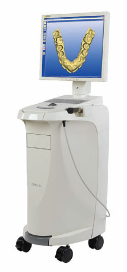 | 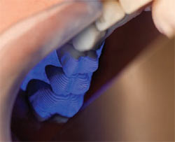 Figure 2 The CEREC AC BlueCam camera captures an image of teeth using a more precise, shorter wavelength blue light source via active triangulation sampling. 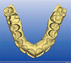 | |||
| Figure 1 The CEREC AC imaging unit. As a CAD/CAM system, the product includes a BlueCam camera and a separate, newly upgraded milling unit, the MC XL. | Figure 3 A screen shot of a full arch showing an onlay preparation on tooth No. 14. Userfriendly tools allow the refinement of a proposed virtual biogeneric restoration before milling. | |||
 | 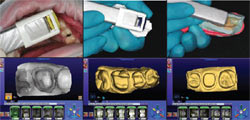 Figure 5 The IntraOral Digitizer, which, in most cases, does not require the use of a reflective powder to capture images, can be used to scan teeth, models, or elastomeric impressions. | |||
| Figure 4 The E4D imaging unit. The CAD/CAM system also includes a separate milling unit for fabricating restorations. | Figure 6 The Autogenesis feature of the E4D system proposes a restoration, which can be enhanced by the operator with simple onscreen tools before milling. | |||
 |  Figure 8 iTero's scanner is used intraorally to capture individual 3D images as the dentist follows voice prompts to assure accurate scanning and occlusal clearance. 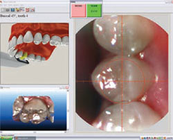 | |||
| Figure 7 The iTero 3D digital impression system. Scan data of preparations are e-mailed wirelessly to Cadent for creation of the model, which then is sent to the laboratory for the restoration. | Figure 9 Typical screen shot of a prepared arch, which may be viewed at any angle using the wireless mouse. | |||
 | 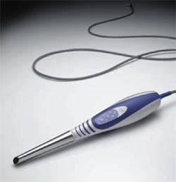 Figure 11 The Lava C.O.S. camera has the smallest wand of any of the reviewed systems, making access to all parts of the oral cavity easier to achieve. 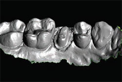 | |||
| Figure 10 The Lava Chairside Oral Scanner (C.O.S.). Note the absence of a keyboard because data entry and laboratory prescriptions are done onscreen. | Figure 12 Typical screen shot of a prepared tooth. In addition to the image shown, the dentist and laboratory technician can view it in stone cast mode or with 3D glasses. | |||
| About the Authors | ||||
| ||||
| ||||
| ||||
| ||||