

The Use of Computerized Treatment Planning and a Customized Surgical Templateto Achieve Optimal Implant Placement
Jack T. Krauser, DMD
Successful prosthetic dental rehabilitation depends on detailed planning that takes into account both anatomic limitations and restorative goals. That planning must be accurately transferred to the surgical field. To facilitate that task, the use of surgical guides has become well-established in implant dentistry.1-7
Over the years, a variety of approaches to implant surgical-guide fabrication have developed. Recent attention has focused on the results that can be achieved by combining computerized tomographic (CT) diagnostic scanning with CAD/CAM and rapid prototyping. Studies by Ganz8-12 have suggested that the use of such technology can improve the outcome of implant placement by helping to ensure that the implant is placed in the best bone volume. The accuracy of these techniques has been confirmed by other research.13,14
Sophisticated three-dimensional (3-D) computer models of oral structures can be generated from CT scan data. Implants can be virtually placed in those computer models (planning images), and the prosthetic result can be instantly assessed, with refinements in positioning made until the placement has been optimized. A surgical guide that allows for precise reproduction of that positioning can then be generated. The NobelGuide™ concept (Nobel Biocare, Yorba Linda, CA) takes this approach further by combining presurgical planning and computerized surgical-guide fabrication with presurgical fabrication of a provisional or final prosthesis that can be delivered at the time of surgery.
MATERIALS AND METHODS
The NobelGuide system enables the surgeon, restorative dentist, and laboratory to share in the diagnosis and treatment planning of each patient receiving implants. All members of the team can assess the 3-D computer model of the patient’s oral structures, in which the bone available for implant placement and the proximity of the placement site(s) to the adjacent dentition, existing implants, maxillary sinus, and inferior alveolar nerve can easily be evaluated. Using the 3-D computer model enables the implants to be placed within the greatest available volume of bone, improving stability. The emergence profile and esthetics can be optimized, with adequate lip support and tongue space ensured.
The NobelGuide approach begins with an evaluation of the patient’s dental esthetics by both the restorative dentist and the patient. The length and shape of the prosthetic teeth, tooth exposure when smiling and talking, the relationship of the teeth to the gingival contours, occlusion, and phonetics are among the factors deserving attention.
Once an ideal restorative outcome has been agreed on, an ideal prototype of the final restoration is fabricated. For fully edentulous cases, it may be possible to revise the patient’s existing prosthesis, rather than creating a new one. A bite registration is made, and a #8 round bur is used to drill 10 to 12 points on the prototype prosthesis. The holes are prepared to a depth of 1 mm and placed in different levels in relation to the occlusal plane. Gutta-percha is flowed into the holes, transforming the prosthesis into a radiographic guide. The NobelGuide Procera® software will later use the radiopacity of these markers to ensure that the prosthesis is properly aligned with the patient’s bone in the computer model.
In preparation for the CT scan, the patient, wearing the prototype prosthesis, is asked to bite evenly and firmly on the bite registration. Either a multi-slice or cone-beam scanner may be used to take the scan. A second CT scan of the prototype prosthesis alone is then taken to compensate for the fact that the acrylic of the prototype in the first scan will become invisible after the Procera software has adjusted the first scan’s density to reveal the presence of the bone. The gutta-percha markers, however, will remain visible. When both scans are imported into the NobelGuide software, the shape of the prosthesis captured in the second scan will be precisely aligned with the image of the surgical site, using the gutta-percha markers as reference points.
Having a 3-D computer model of the bone in relation to the ideal prosthesis gives the surgeon an invaluable tool for deciding where the implant(s) should be placed for optimal anchorage, provision of support for the prosthesis, and placement for a superior restorative outcome. Alternatively, the computer model may reveal that grafting is necessary. Either the surgical or the restorative dentist may do the initial planning, and then the computer model can be shared with the other team member(s).
After a final decision has been made about the implant’s positioning, the Procera software creates a rendition of a surgical guide that will enable placement of the actual implants precisely in the predetermined positions and orientations. A computer file containing the 3-D model of this surgical guide is then transmitted electronically for rapid prototyping by Nobel Biocare. Once fabricated, the surgical guide is sent to a dental laboratory trained in working with the NobelGuide concept to make the surgical index (a special bite registration created on the articulator) and the master cast from which the restoration will be created.
After the master cast has been made, the surgical guide is returned to the surgeon. During implant-placement surgery, the surgical guide is positioned using a surgical index and secured with guided anchor pins. The minimally invasive guided surgery is accomplished by using NobelGuide instrumentation and drilling sequentially with increasing diameters. The im-plants are then inserted, and the temporary or final premade restoration is delivered.
The NobelGuide system is not currently indicated for implant placement immediately after extraction. It can be used when treating partially and fully edentulous ridges, as well as single-implant placement sites anywhere in the mouth.
CASE REPORT
The patient was a 56-year-old woman who had been fully edentulous for a number of years. Her mandible had been restored with four implants and a bar-supported overdenture. Tired of the instability of her removable maxillary denture (Figure 1), she sought an implant-supported solution.
Clinical examination of the edentulous arch (Figure 2) revealed a thick, healthy ridge. The tissue firmness and tone were ideal, with no preprosthetic surgery indicated. The patient was advised that she appeared to be an ideal candidate for Teeth-in-an-Hour™ (Nobel Biocare), and she chose that option.
The patient’s dental esthetics were evaluated, and it was decided to modify her existing denture, adjusting the contours and relining the intaglio surface with a soft-line material to achieve an intimate fit with her soft tissue. Because of the soft lining, it was necessary to duplicate the optimized denture in hard clear acrylic (the exact thickness of the gingival and palatal tissue cannot be identified precisely with a soft-lined prosthesis). Ten gutta-percha radiographic markers were added to the clear acrylic denture, and it was tried in (Figure 3).
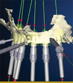
In the offices of the surgeon, an i-CAT CT scan (Imaging Sciences International, Inc, Hatfield, PA) was taken of the patient wearing the radiographic guide with the bite registration. The radiographic guide alone was then scanned. The data from the scans were loaded into the NobelGuide Procera software. Three-dimensional images of the patient’s bone and the optimized denture were generated within the planning software. The plan consisted of three anchor pins and six definitive implants that were then placed virtually (Figure 4).
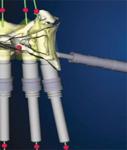
The NobelGuide Procera software gives the user the power to turn various layers of the 3-D computer model off and on, an important capability when evaluating whether implant placement has been optimized. Figure 4 and Figure 5 are different views of the same computer model, for example. The difference between them is that in Figure 5 the prosthesis has been removed, revealing the positioning of the implants in the bone. This view makes it clear that the first, second, and fifth implants (going from left to right) are well positioned, but the fourth and sixth implants have been positioned too far labially, and the inclination of the third implant is tilted too far to the labial.
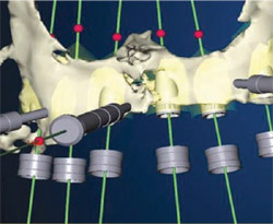
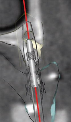
Altering the position of the implant in the computer model is easy to do. Figure 6, for example, is a two-dimensional (2-D) facial-to-palatal slice that was taken from the 3-D image seen in Figure 5. While the 2-D image cannot be rotated (as can the 3-D), the implant inclination can be changed by clicking on one of the red dots near the bottom of the screen and pulling it facially or palatally (the red dot at the top of the screen is the fulcrum point). As the implant inclination is changed, the position of the implant within the bone changes before the viewer’s eyes, so an appropriate inclination can be readily determined. The prosthesis can then be added to the image (Figure 7) to confirm the emergence profile and the alignment of the implant to the ultimate final prosthesis. Alternating between views of the prosthesis on and off while adjusting the implant placement allows for clinical skills and experience to be married to the virtual planning capabilities of the software.
Changing the depth of an implant is equally intuitive. The software user clicks on the thin green line that runs through the implant and moves it apically or coronally.
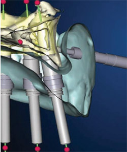
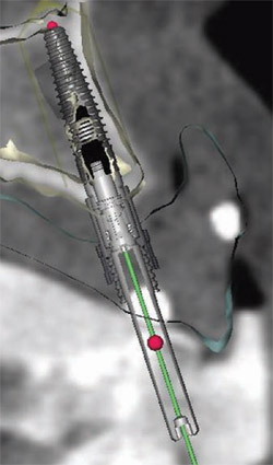
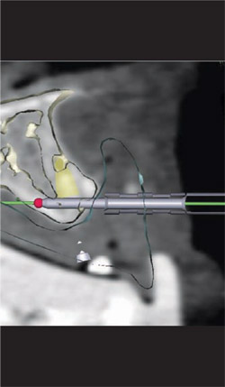
Numerous other views of the implants being placed are accessible with the Nobel-Guide Procera software. In Figure 8 , the fixture mounts have been removed from the 3-D image. The rings that appear to be floating in space are the sleeves that will be incorporated in the surgical guide to help place the actual implant precisely, controlling the angulation, mesial-distal positioning, and depth. By rotating the 3-D image, the palatal aspect of the computer model can also be assessed, as in Figure 9 . Yet another view is accessible by using the software’s “reslice” tool, as has been done in Figure 10 ; Figure 11 ; Figure 12 . This tool makes the images more closely resemble a traditional radiograph, with which most clinicians are more accustomed to working. The reslice tool can be moved around the arch, allowing for various cross-sectional slices. This allows for placement of the implants around the arch.
After the ideal positioning was agreed on, the computer file of the patient’s case was sent via the Internet to Nobel Biocare manufacturing, where a surgical guide was fabricated from acrylic resin using stereolithography technology. Metal sleeves were added to the surgical guide, which was then sent to the surgeon. The surgeon tried in the surgical guide on the patient, and during the same visit a polyvinylsiloxane surgical index was created. This was to be used during surgery to stabilize the surgical guide in the patient’s mouth against the lower prosthesis until the anchor pins were inserted.
The verified guide was forwarded to the laboratory, where a technician inserted implant analogs and anchor pins into it (Figure 13), and soft-tissue cast material was added (Figure 14) to create the gingival aspect of the master cast. The master cast was then created (Figure 15). The master cast and the acrylic framework were scanned with a Procera® Forte Scanner (Nobel Biocare), capturing the contours of the gingiva and the exact position and orientation of the implants. The digital information was sent to Nobel Biocare’s milling facility in Mahwah, NJ, where the framework for the final restoration was milled from a solid piece of titanium. The framework was returned to the dental laboratory, where it was tried in on the master cast, and a passive and precise fit was confirmed. Teeth were added, in accordance with the preprosthetic plan agreed on by the dentist and the patient.
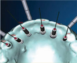
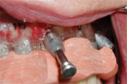
On the day of surgery, local anesthesia was administered about 10 minutes before starting the procedure to allow for dissipation of the anesthetic. The surgical guide and surgical index were seated into the patient’s mouth, and the patient was instructed to bite down on the surgical index (Figure 16 and Figure 17). The three guided anchor pins were then placed after preparation with a depth-controlled 1.5-mm twist drill (Figure 18). The lower denture and surgical index were removed, and osteotomies were created at the second and fifth implant positions by using the NobelGuide drills through the sleeves in the surgical guide. The sleeves control not only the position and angulation of the drilling, but also the depth.
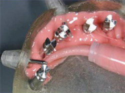
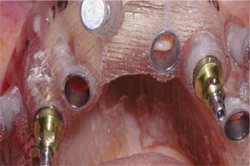
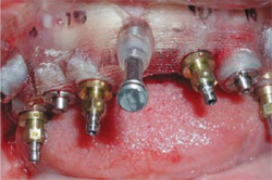
A 4.3-mm-diameter NobelReplace™ Tapered implant (Nobel Biocare) was placed in both the second and fifth positions. The fixture mounts were removed and special template abutments were connected. The template abutments, when tightened, lock to the surgical guide providing additional vertical stability and anchorage. At this point, the surgical guide was extremely stable. Four additional 4.3-mm NobelReplace Tapered implants were inserted (Figure 19), completing the surgical operation.
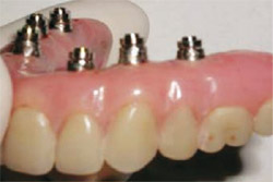
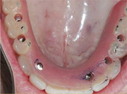
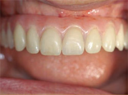
The fixture mounts and template abutments were removed, along with the anchor pins and the surgical guide. Soft tissue tags were removed with a tissue punch (a blade can also be used to accomplish this). The final prosthesis was delivered (Figure 20). Note that the final prosthesis was retained using special guided abutments (Figure 21) that can move vertically 0.4 mm to compensate for any compressive distortion that may have occurred from soft tissue. The guided abutment screws were torqued to 35 Ncm. The patient was dismissed with instructions to eat a normal diet but avoid chewing on excessively hard foods for approximately 2 months to avoid interfering with the osseointegration process. Figure 22shows the final restoration in place.
DISCUSSION
The flapless surgery enabled by the NobelGuide system offers a number of advantages to both the implant team and the patient. Because the surgery is minimally invasive and requires no suturing, patients typically experience no significant pain or swelling. In addition, receiving an immediate restoration enables most patients to avoid any disruption of their normal work and social lives, a significant cost savings for many. Fewer appointments and reduced chairtime are both attractive features of this system.
The NobelGuide approach allows the implant team members to offer these benefits (and thus expand their practices) while enjoying a high degree of confidence that adequate implant support can be achieved and an esthetic restoration delivered. The ability to coordinate the case-planning between the surgical and res-torative dentists and the laboratory further reduces the opportunities for miscommunication, and allows the teammates to coordinate product inventories and other aspects of patient care.
Although the greatest amount of information and, hence, predictability is achievable by using the CT scans to generate a computer-based planning model, it is possible to use the NobelGuide surgical protocol and instrumentation to improve placement predictability and accuracy for surgeries that have been traditionally planned on a model. Flapless surgery and delivery of an immediate restoration can also be offered in such cases, assuming that careful preoperative evaluation and diagnostic radiographic imaging have confirmed the presence of adequate bone volume and revealed no other contraindications. Prosthetic alternatives are feasible as well.
Regardless of how the surgery is planned, use of the NobelGuide system does not require placement of a final restoration at the time of surgery. A temporary restoration can be used or non-esthetic areas may be left untemporized. However, immediate function has been extensively documented to be both safe and predictable,15-19 and it offers the patient the cited advantages.
Note that if bone volume is not adequate and augmentation must be undertaken, use of the NobelGuide approach is not indicated until after the grafted site(s) have completely healed.
It is important to note that when using a computer-based model for planning, the accuracy of the model depends on proper CT scanning procedures. The radiographic guide also must be fabricated and positioned properly. As the presence of CT scanners becomes more common in dental offices, ensuring that the NobelGuide scanning protocol is properly carried out should also become easier.
CONCLUSION
The NobelGuide system gives implant teams a detailed 3-D computer model of a patient’s oral structures that provides invaluable guidance when planning implant placement. The computer model makes it possible to see the prosthetic outcome of a variety of placement options. Once a plan has been agreed on, a computer-fabricated surgical guide enables the procedure to be carried out in a highly precise manner. A final restoration can be delivered at the time of surgery, if desired. The system is highly accurate and predictable, easy to use, and results in benefits for both patients and dental practitioners.
ACKNOWLEDGMENT
The author would like to thank Dr. David Skopp, Palm Beach Gardens, FL (prosthetics) as well as Hennessy Dental Laboratory, West Palm Beach, FL.
References
1. Federick DR, Del Rey M. A surgical guide for insertion of implant fixtures. Implant Dent. 1992;1(2):129-131.2. McKinstry RE, Zini I. A homemade microwaveable denture reline jig. J Prosthet Dent. 1992;67(2):269-274.
3. McMillan AS, Walton JN. Fabrication of an implant surgical guide using a denture replica technique. Quintessence Int. 1994;25(9):611-615.
4. Becker CM, Kaiser DA. Surgical guide for dental implant placement. J Prosthet Dent. 2000;83(2):248-251.
5. Koyanagi K. Development and clinical application of a surgical guide for optimal implant placement. J Prosthet Dent. 2002;88(5): 548-552.
6. Shotwell JL, Billy EJ, Wang HL, Oh TJ. Implant surgical guide fabrication for partially edentulous patients. J Prosthet Dent. 2005;93(3): 294-297.
7. Atsu SS. A surgical guide for dental implant placement in edentulous posterior regions. J Prosthet Dent. 2006;96(2):129-133.
8. Ganz SD. The triangle of bone—a formula for successful implant placement and restoration. The Implant Society, Inc. 1995;5:(2):2-6.
9. Ganz SD. CT scan technology—an evolving tool for predictable implant placement and restoration. International Magazine of Oral Implantology. 2001;1:6-13.
10. Ganz SD. Use of stereolithographic models as diagnostic and restorative aids for predictable immediate loading of implants. Pract Proced Aesthet Dent. 2003;15(10):763-771.
11. Ganz SD. Presurgical planning with CT-derived fabrication of surgical guides. J Oral Maxillofac Surg. 2005;63(9 Suppl 2):59-71.
12. Ganz SD. Techniques for the use of CT imaging for the fabrication of surgical guides. In: Atlas of the Oral and Maxillofacial Surgery Clinics of North America. Atlanta, GA; Elsevier Saunders: 2006;14:75-97.
13. Sarment DP, Sukovic P, Clinthorne N. Accuracy of implant placement with a stereolithographic surgical guide. Int J Oral Maxillofac Implants. 2003;18(4): 571-577.
14. van Steenberghe D, Glauser R, Blomback U, et al. A computed tomographic scan-derived customized surgical template and fixed prosthesis for flapless surgery and immediate loading of implants in fully edentulous maxillae: a prospective multicenter study. Clin Implant Dent Relat Res. 2005;7(Suppl 1):111-120.
15. Lee CY. Immediate load protocol for anterior maxilla with cortical bone from mandibular ramus. Implant Dent. 2006;15(2):153-159.
16. Lozada J, Ardah A, Rungcharassaeng K, et al. Immediate functional loading of mandibular implant overdentures: a surgical and prosthodontic rationale of 2 implant modalities. J Oral Implantol. 2004;30(5):297-306.
17. Locante WM. Single-tooth replacements in the esthetic zone with an immediate function implant: a preliminary report. J Oral Implantol. 2004;30(6): 369-375.
18. Ganeles J, Wismeijer D. Early and immediately restored and loaded dental implants for single-tooth and partial-arch applications. Int J Oral Maxillofac Implants. 2004;19(Suppl):92-102.
19. Degidi M, Piatelli A. Comparative analysis study of 702 dental implants subjected to immediate functional loading and immediate nonfunctional loading to traditional healing periods with a follow-up of up to 24 months. Int J Oral Maxillofac Implants. 2005;1: 99-107.
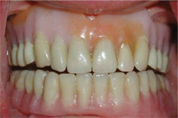 | 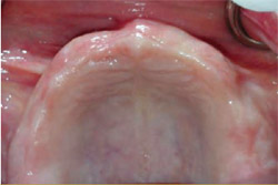 | |
| Figure 1 The patient was seeking a more stable replacement for her removable maxillary denture. | Figure 2 The edentulous ridge was thick, with healthy tissue and ideal tone. | |
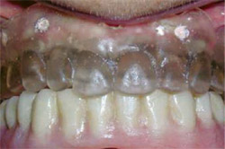 | ||
| Figure 3 Some of the gutta-percha markers can be seen in the clear acrylic radiographic guide. | ||
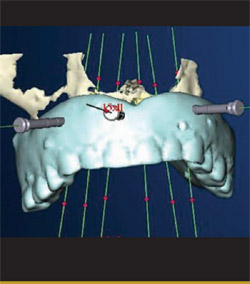 |  | |
| Figure 4 Three-dimensional image of the planned ideal prosthesis, anchored by six implants that were placed virtually in the computer model of the patient's bone. | Figure 5 A view of the same image shown in Figure 4, with the image of the virtual prosthesis turned off. Note that at this point the positioning of the third, fourth, and sixth implants had not yet been optimized. | |
 |  | |
| Figure 6 Two-dimensional facial-to-palatal slice taken from the image seen in Figure 5.The inclination of any of the implants can be changed by clicking on one of the red dots and rotating it facially or palatally. | Figure 7 The same image as in Figure 6, with the image of the prosthesis turned on. | |
 |  | |
| Figure 8 In this image, the fixture mounts have been turned off. The rings are the sleeves that would be incorporated into the surgical guide to control the positioning, angulation, and depth of the implant placement. | Figure 9 The computer model was rotated to reveal the palatal view of the proposed implants' emergence. | |
 |  | |
| Figure 10 Activating the software's reslice tool makes the images more closely resemble a traditional radiograph. | Figure 11 Two-dimensional view of a guided anchor pin in position, with the reslice tool activated. | |
 | 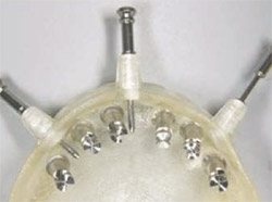 | |
| Figure 13 Implant analogs and anchor pins were inserted into the surgical guide. | ||
 | ||
| Figure 14 Soft-tissue mask material was added to the surgical guide. | ||
| Figure 12 With the reslice tool activated, this 2-D cross-sectional view shows the position and depth of the guide sleeve within the body of the prosthesis. Note that the implant is within the triangle of best available bone, and that the placement meets the anatomical, surgical, and prosthetic requirements. | ||
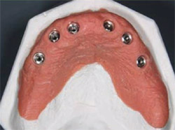 | 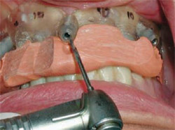 | |
| Figure 15 The master cast was fabricated using the surgical guide. Data from a scan of this cast would be used to mill a framework from a single piece of titanium. | Figure 16 Guided anchor pins were placed with a depth-controlled 1.5-mm twist drill. | |
 |  | |
| Figure 17 The surgical guide stabilized by the surgical index against the lower denture is secured with a guided anchor pin. | Figure 18 The implants in the second and fifth positions were placed first. | |
 |  | |
| Figure 19 The implants in the second and fifth positions were secured with template abutments, and four additional implants were placed. The combination of the template abutments and the anchor pins (also visible) makes the surgical guide extremely stable. | Figure 20 Special guided abutments secured the prosthesis to the implants with 0.4-mm vertical correction possible. | |
 |  | |
| Figure 21 The final prosthesis being delivered to the mouth. | Figure 22 The final restoration in place, less than 1 hour after initiation of the surgery. | |
| About the Author | ||
 Jack T. Krauser, DMD Jack T. Krauser, DMDPrivate Practice Periodontics, Tissue Regeneration, and Guided Implant Surgery Boca Raton, Florida | ||

