
Microscope-Enhanced Endodontic Therapy: MEET©ing the Challenge of Clinical Practice
Stephen P. Niemczyk, DMD
While much has been written about cutting-edge instrumentation and obturation techniques as well as their development and efficacy, they are anticlimactic when considered in the overall picture of endodontic treatment. The recognition and disclosure of all potential canal locations has always been, until recently, the paramount challenge in successful root canal therapy. Indiscriminate excavations often resulted in perforations of the furcation or, in the attempt at separated instrument retrieval, inadvertent egress through the side of the root. The lack of sufficient magnification with concomitant illumination further compounded the difficulties encountered during conventional nonsurgical procedures. Failure to recognize and act upon visual cues not discernable to the unassisted naked eye yielded less than desirable results.
The turning point occurred in 1981, when the advantages of an operating microscope for use in dentistry were presented by Apotheker and Jako.1,2 Their work led to the development of the Dentiscope (Chayes-Virginia Inc, Evansville, IN), a binocular microscope with built-in fiber-optic illumination and a magnification factor of 7X normal view (Figure 1). Early proponents of this instrument reported on the increase in quality and precision,3,4 attaining “levels of perfection never dreamed possible.”3
So profound is its impact that, since 1995, the American Association of Endodontists has required that all postgraduate students demonstrate proficiency in its use before graduation. Endodontists can now observe in a clinical setting what they previously could only witness in textbooks, and treat at a level never before realized by their predecessors. It is the goal of this article to present examples of “rediscovered” anatomical clues, methods used to disclose potential canal orifices within the pulp chamber, and the different techniques used to address the nonsurgical diagnosis of crown-root fractures and the treatment of calcified canals, furcation perforations, and separated instrument retrieval.
Access and Canal Location
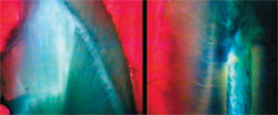
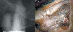
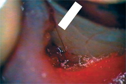
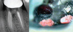
Exposure of the pulp chamber may define access, but the refinement of its boundaries and the disclosure of all of the canal orifices is an important prologue to all of the instrumentation that follows. The implementation of the operating microscope has redefined traditional percentages with regard to canal numbers and location, reflecting greater incidences of fourth canals in posterior teeth than was previously thought.5 Extrapolation of surgical observations of a structure termed an “isthmus” has also led to the discovery of negotiable spaces originating within the floor of the pulp chamber.6 Lack of disclosure and subsequent treatment of these tissue-containing entities plays a major role in the failure of a therapy that radiographically appears complete. In the exploration of the chamber floor, the first visual clue is what appears to be a line on the pulpal floor, termed the pulpal map (Figure 2). These dark lines are not stains in the floor, but a light-diffraction phenomenon. When subjected to incident light, the curving orientation and invagination of the dentinal tubules forming the furcation bend the light to varying degrees, creating these lines between the canal orifices. This effect can be confirmed by transillumination of an extracted tooth, where these lines all but disappear (Figure 3). Discontinuity of this line may indicate an overhanging portion of the chambers’ roof, warranting closer inspection and removal to uncover hidden canal orifices.
Once the chamber’s periphery is defined, higher-power observation of the intact floor will disclose discreet bleeding points in vital teeth or tissue tags remaining in nonvital cases. Often these are the first indications of canal orifices, verified by a sharp dental explorer or insertion of a small hand instrument such as a No. 10 K-file. The bleeding tissue from a canal in an intact floor should not be confused with that created from a perforation. The intact furcation is often a French Gray color, whereas a perforation is surrounded by a thinner segment of pale pink dentin, which appears as a halo around the perforation site.
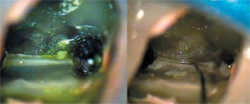
Dyes such as methylene blue have been suggested for disclosing structures, including fractures, canal orifices, and isthmuses, but are in reality an indiscriminate stain.7 Other agents are available that react more reliably with the suspect tissue. One of these is sodium hypochlorite (NaOCl). Traditionally used for root canal debridement, its action on vital and nonvital tissue is digestive in nature. A by-product of this digestion is the formation of small bubbles or effervescence wherever tissue is present. The coalescence of these small bubbles can be seen foaming in the pulp chamber with the naked eye, but it is the origin of the bubble stream that is important. At higher magnification, the base of a minute hypochlorite plume can be discerned on the floor of the chamber and explored with a small instrument such as a DG-16 explorer or D-11T spreader (Figure 4). Once a space is created, confirmation of a canal can be obtained by threading a small hand file apically within the space and confirming a length with an apex locator.
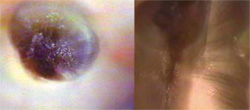
An even more discreet dye is fluorescein sodium (Ful Glo®, Akorn Inc, Somerset, NJ), which is used routinely in ophthalmology practice. It is applied to the eyes of patients who wear contact lenses to disclose tears in the sclera or cornea.8,9 It has an affinity for disruptions in connective tissue and, when subjected to black-light illumination, fluoresce a chartreuse green color. This property makes it an ideal disclosing agent for canal orifices, where the tearing of pulp tissue during access creates connective tissue stumps at the coronal extent of each canal system. The liquid can be obtained either as ready to use in a vial or as a dried precipitate on a paper strip. Because the vials have a shelf life and are not sterile once opened, the preferred method is the reconstitution of the chemical by dipping the paper strip in a dappen dish containing alcohol. The prepared liquid is then delivered to the chamber with a micropipette or dropper, and the excess evacuated with suction only. The chamber is then illuminated by the beam of a composite curing light while observing through the microscope (Figure 5). The glowing chartreuse tags are indicative of tissue locations and warrant further scrutiny. This technique is particularly useful in the acquisition of “extra” canals within a root. Reported in the literature as three-canal mandibular or maxillary roots, they are, in fact, extensions of an existing isthmus that originates from the pulp chamber.10,11 These third canals are detected with the fluorescein sodium dye, and investigation often yields a space that can be readily negotiated to the root terminus (Figure 5 and Figure 6).
Calcified Canals
Gaining access to pulp chambers and canal orifices once they have been dystrophically obliterated is one of the most daunting challenges in endodontic therapy. External landmarks are useful only if the crown of the tooth is intact, and the traditional “hunt-and-peck” methods of excavation often yield less than desirable results. Radiographs are of limited value, and the dentin color of the access appears monochromatic to the naked eye.
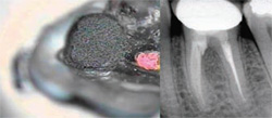
However, at higher magnification, the dystrophic dentin comprising the obliterations has a distinctly different hue from either the original or secondary dentin. This is a result of the haphazard nature of its formation, and the resultant light diffraction difference. It will appear either lighter or darker than the surrounding dentin, outlining the original perimeter of the chamber or orifice. Another location technique relies on a histological phenomenon the author terms “radial dentin.” In a ground section of the crown of a tooth, the dentinal tubules array themselves like a fan from the pulp chamber to the dentin-enamel junction (DEJ). However, at the level of the DEJ, the tubules assume a more perpendicular arrangement with respect to the canal space (Figure 7). When viewed from within the access, this tubule arrangement appears as a “sunburst” effect, with the tubules radially arranged with respect to the original canal location. In an anterior tooth, confining the excavation within the limits of this radial dentin and concomitant dystrophic deposits will safely guide the clinician apically to a more patent section of the root canal space. In posterior teeth, this radial dentin serves to define the pulp chamber and limits of the canal system in a multicanal root (Figure 8). The higher magnifications used in the discovery process have the disadvantage of a limited field of view, which contraindicates the use of a conventional high-speed handpiece for access into the root. Instead, specialized ultrasonic tips in various configurations are used for this purpose, providing discreet and precise dentin removal while allowing unobstructed observation (Figure 9 and Figure 10).
Crown-Root Fracture
The diagnosis of “cracked tooth” is often made without substantive corroboration to justify the patient’s signs and symptoms. The deep, isolated periodontal probing depth and clinical/radiographic separation of segments are not present in the early stages of the fracture’s progression. The initial presenting symptoms may mimic those of a faulty restoration or malocclusion, further clouding the diagnostic picture. Removal of the intracoronal restoration in a suspect tooth and inspecting the surface without magnification is often inconclusive. When the tooth is restored with a full-coverage crown, the definitive diagnosis can only be obtained through surgical reflection of the overlying tissue.
Higher magnification now affords the operator the opportunity to critically examine all exposed surfaces, including those in the gingival sulcus. Once the source of the symptoms has been isolated to one tooth, higher-power observation may reveal the presence of small lines or fractures in the enamel surface. Staining with a dye such as methylene blue will differentiate these true, incipient fractures from the nonpathologic infractions termed “craze lines.” These true fractures are often cariously involved, with a darker intrinsic stain coincident with the course of the fracture into the underlying dentin layer (Figure 11). Once disclosed, an attempt should be made to ascertain the extent of the fracture by preparation into the line and/or removal of the adjacent restoration. It is not uncommon to expose the pulp chamber during this procedure, and the patient should be apprised of this possibility before the excavation.
If the pulp chamber is exposed, it can afford an uncompromised evaluation of the fracture’s extent once the bleeding from the pulpal tissues is controlled. If the fracture extends into one of the canal orifices, especially a distal or palatal canal, the prognosis for long-term retention is poor (Figure 11View Figure). Hemisection in these instances may not be feasible because of anatomic or occlusal restraints and placement of a full-coverage restoration, with very few exceptions, serves only to delay the inevitable extraction.
Once the pulp chamber is open, a distinction should be made between a true fracture and a histological entity called a “dead tract.” They are similar in appearance, especially when observed with unassisted vision. The difference is in their etiology. A dead tract is a dentinal tubule devoid of its odontoblast process as a result of a restorative or carious insult. It is darker than the surrounding tubules because the remaining nonvital contents of the tubule reflect the incident light differently than the intact structure. A fracture is the longitudinal separation of these tubules, usually accompanied by bacteria and debris. The differential diagnosis can be obtained by flooding the chamber with NaOCl and observing the reaction on the suspected site at higher power. A true fracture will manifest a small effervescent line along the course of the fracture, owing to the reaction of the tissue present with the hypochlorite. In contrast, an intact dead tract will not present this reaction interface; consequentially, it fails to exhibit the same bubbling effect (Figure 12).
Traditionally, a crowned tooth suspected of fracture confounded the diagnosis. Oftentimes, surgical reflection of the site was the only means to achieve direct observation of the fracture line emanating from the crown margin apically along the root surface. The operating microscope now presents a more conservative alternative. Once the offending tooth has been isolated, the gingival tissues of the sulcular crest are examined. Inconsistencies in the color or texture are indicative of an underlying etiology, which can be an open margin, calculus deposit, or fracture. The gingival tissue exhibits microedema, and striation of the vasculature is often observed at the crest. Using an endodontic excavator or periosteal elevator, this swollen tissue is reflected apically a few millimeters to visualize the root surface. With the aid of higher-power magnification, fractures under a crown margin are easily diagnosed and can be readily stained by the occult blood in the site or with methylene blue dye (Figure 13). This process is achieved without overt surgical incision and reflection of the gingiva and potential postoperative complications.
Furcation Perforations
It is not uncommon for perforations to occur during the access of pulp chambers in teeth that have been dystrophically obliterated. Conventional techniques for repair of these iatrogenic communications included amalgam, zinc oxide eugenol, acid-etch composite, and glass ionomer.12-15 Emphasis was on the occlusion of the opening, rather than the biologic reconstruction and regeneration of the underlying hard and soft tissues. Lack of periodontal attachment to the material used to seal the perforation site provided the nidus for further breakdown and eventual communication with the gingival sulcus.
There is now a material, mineral trioxide aggregate (MTA), which is marketed under the trade name ProRoot® MTA (Dentsply Tulsa Dental, Tulsa, OK), that satisfies the physical requirements for closure as well as the biologic environment for soft and hard tissue reapproximation over the repair material. Developed as a surgical root-end filling material, its use has expanded into pulp capping/pulpotomy treatment, apexification procedures, and perforation repair. It is highly biocompatible, demonstrating in the animal models overgrowth of tissue onto the MTA and regeneration of normal architecture at the site of placement.16-21 It is available in two forms: a gray formulation having the consistency of damp sand and a white variation with a finer grain similar to orthodontic plaster. This latter form is most often used in anterior applications, but both forms exhibit identical biologic properties.
In the repair of a perforation, timing is a key factor. Affecting repair within 24 hours of the incident presents the best prognosis;22,23 ideally, the site should be sealed with MTA immediately upon recognition of the mishap.24,25 This will prevent percolation through the site, formation of granulation tissue, and subsequent periodontal detachment. In the event the definitive repair cannot be affected within the prescribed time period, sealing the site with any material that is easily retrieved will prevent this percolation effect. Providing an inordinate amount of time does not elapse before replacement with MTA, this temporary repair will also yield acceptable results.
MTA material requires approximately 4 hours of setting time;26,27 therefore, overt bleeding into the repair site will dilute the MTA and compromise the intended seal. It is imperative that the bleeding be controlled with a relatively benign hemostatic agent, such as aluminum chloride or, in the case of a large perforation, a collagen-based membrane. This latter application provides the required hemostasis as well as support for the condensation of the MTA into the repair site. However, care must be taken to avoid overlap of the collagen membrane over the cavosurface of the perforation because this can create a potential void in seal integrity when the collagen is resorbed.
Once hemostasis is achieved, the MTA should be delivered to the site in small increments with an amalgam carrier that is used exclusively with the MTA material. A carrier that has previously transported amalgam contains remnants of that material on the barrel walls, and contamination of the MTA mixture is easily recognized by the streaks of amalgam on the surface of the pellet. There are also syringe-type carriers specifically designed for use with MTA, with tips that have surgical and nonsurgical applications (MAP system, Roydent Dental Products, Johnson City, TN). The MTA should be gently adapted and condensed into the site, the excess removed, and the repair site covered with a glass ionomer or composite restoration (Figure 14 and Figure 15). Previous protocols required a moist cotton pledget placed on top of the MTA to provide moisture for the setting reaction; however, a recent study has discounted this step as unnecessary because of the moist environment on the tissue side of the repair.28 If etching of the chamber walls is required, it should be performed before placement of the MTA. This will prevent washout of the repair material during the rinsing of the acid-etch.
Separated Instrument Retrieval
There are two categories of practitioners who perform root canal therapy: those who have separated an instrument and those who will in the future. Regardless of the care taken and caution not to reuse stressed files, at one time or another we have all left a “souvenir” behind. Traditional removal techniques using trephination enjoyed limited success, often disemboweling the root, perforating laterally, or perpetrating fractures.
The same techniques and armamentarium used to uncover calcified canals are implemented in the recovery of instrument fragments. The caveat is that “you need to see it to retrieve it.” You must be able to uncover and visualize the coronal 2 mm to 3 mm of the file to strategically place an ultrasonic (US) tip against the file’s flutes. Initially this space is created coronal to the fragment with Gates Glidden (GG) burs, with a modified GG used to create a flattened staging platform (Figure 16). Small ultrasonic tips designed for deep excavation within the root are then engaged to create a circumferential trough 2 mm to 3 mm deep around the fragment end (Figure 17). A smooth-sided US tip energized at a lower power setting is then brought to bear against one flute of the file, gently nudging it in a counter-clockwise direction until the fragment dislodges (Figure 18). Application of the vibrations should be intermittent to avoid overheating the dentin or the fragment. This is especially true with nickel titanium files. Subject to excessive vibration, these files will fragment at the point of application, requiring deeper restaging and troughing. In assessing retrieval potential, the shorter and more tapered the fragment, the more likely it is to become dislodged when the vibrations are applied. Lastly, attempts at retrieval without the aid of a microscope or ultrasonics, regardless of the depth of separation, are ill-advised.
Conclusion
The use of the microscope and its inherent precision is closing the gap between theoretical possibility and clinical reality. Its acceptance into everyday endodontic practice has catapulted treatment to new levels heretofore deemed unattainable. It is only a matter of time before it is integrated into all other disciplines of dental practice as well.
References
1. Apotheker H, Jako GJ. A microscope for use in dentistry. J Microsurg. 1981;3(1):7-10.2. Apotheker H. The applications of the dental microscope: preliminary report. J Microsurg. 1981;3(2):103-106.
3. Selden HS. The role of the dental operating microscope in endodontics. Pa Dent J (Harrisb). 1986;53(3):36-37.
4. Selden HS. The role of the dental operating microscope in improved nonsurgical treatment of “calcified” canals. Oral Surg Oral Med Oral Pathol. 1989;68(1):93-98.
5. Stropko JJ. Canal morphology of maxillary molars: clinical observations of canal configurations. J Endod. 1999;25(6):446-450.
6. Weller RN, Niemczyk SP, Kim S. Incidence and position of the canal isthmus. Part 1. Mesiobuccal root of the maxillary first molar. J Endod. 1995;21(7):380-383.
7. Kim S. Principles of Endodontic Surgery. In: Microscopes in Endodontics, The Dental Clinics of North America. W.B Saunders 1997:484-485.
8. Schnider CM. Dyes. In: Clinical Ocular Pharmacology, 3rd ed. Boston, Mass: Butterworth-Heinemann; 1995:389-407.
9. Albert DM, Jakobiec FA. Conjunctiva, Cornea and Sclera. In: Principles and Practice of Ophthalmology, Vol 1. Philadelphia, Penn: W.B. Saunders Co; 1994: 10-11.
10. Ricucci D. Three independent canals in the mesial root of a mandibular first molar. Endod Dent Traumatol. 1997;13(1):47-49.
11. Ferguson DB, Kjar KS, Hartwell GR. Three canals in the mesiobuccal root of a maxillary first molar: a case report. J Endod. 2005;31(5):400-402.
12. Jew RC, Weine FS, Keene JJ Jr, et al. A histologic evaluation of periodontal tissues adjacent to root perforations filled with Cavit. Oral Surg Oral Med Oral Pathol 1982;54(1):124-135.
13. Sinai IH. Endodontic perforations: their prognosis and treatment. J Am Dent Assoc. 1977;95(1):90-95.
14. Mitsis FJ. Flap operation techniques for the treatment of certain endodontic and periodontic problems. J Brit Endod Soc. 1970;4(1):6-9.
15. Benenati FW, Roane JB, Biggs JT, et al. Recall evaluation of iatrogenic root perforations repaired with amalgam and gutta percha. J Endod. 1986;12(4): 161-166.
16. Torabinejad M, Hong CU, Pitt Ford TR, et al. Tissue reaction of implanted super-EBA and mineral trioxide aggregate in the mandible of guinea pigs: a preliminary report. J Endod. 1995;21(11):569-571.
17. Torabinejad M, Pitt Ford TR, McKendry DJ, et al. Histologic assessment of mineral trioxide aggregate as a root-end filling in monkeys. J Endod. 1997;23(4):225-228.
18. Torabinejad M, Hong CU, Lee SJ, et al. Investigation of mineral trioxide aggregate for root end filling in dogs. J Endod. 1995;21(12): 603-608.
19. Torabinejad, M, Pitt Ford TR, McKendry DJ, et al. Histologic assessment of mineral trioxide aggregate as root end filling in monkeys. J Endod. 1997;23(4): 225-228.
20. Torabinejad M, Hong CU, Pitt Ford TR, et al. Antibacterial effects of some root end filling materials. J Endod. 1995;21(8);403-406.
21. Holland R, de Souza V, Nery MJ, et al. Reaction of dogs’ teeth to root canal filling with mineral trioxide aggregate or a glass ionomer sealer. J Endod. 1999;25(11): 728-730.
22. Torabinejad M, Chivian N. Clinical applications of mineral trioxide aggregate. J Endod. 1999;25(3):197-205.
23. Tidmarsh B. Accidental perforation of the roots of teeth. J Oral Rehabil. 1979;6(3):235-240.
24. Lee SJ, Monsef M, Torabinejad M. The sealing ability of a mineral trioxide aggregate for repair of lateral root perforations J Endod. 1993;19(11):541-544.
25. Ford TR, Torabinejad M, McKendry DJ, et al. Use of mineral trioxide aggregate for repair of furcal perforations. Oral Surg Oral Med Oral Pathol Oral Radiol Endod. 1995;79(6):756-763.
26. Torabinejad M, Watson TF, Pitt Ford TR. Sealing ability of a mineral trioxide aggregate when used as a root end filling material. J Endod. 1993;19(12): 591-595.
27. Torabinejad M, Hong CU, McDonald F, et al. Physical and chemical properties of a new root-end filling material. J Endod. 1995;21(7):349-353.
28. Witherspoon DE, Ham K. One-visit apexification: technique for inducing root-end barrier formation in apical closures. Pract Proced Aesthet Dent. 2001;13(6):455-460.
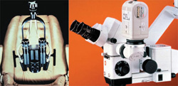 | 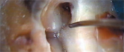 | |
| Figure 1 Dentiscope (left) and a modern surgical operating microscope (right). Aside from the increase in illumination and magnification, the modern microscope can be equipped for various media documentation. | Figure 2 The pulpal map under incident light. The dental explorer is outlining an overhang of the access wall that covers the MB2 canal. | |
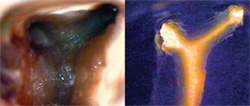 |  | |
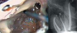
| Figure 3 The pulpal map, seen with incident light on the left, appears as a dark line connecting the canal orifices. When viewed with transmitted light from the furcation (right), the dark line disappears. | Figure 4 Excess NaOCl has been removed from the chamber of a maxillary molar, with effervescence evident between MB1 and MB2. Final instrumentation revealed a three-canal MB root (right). | |
 | 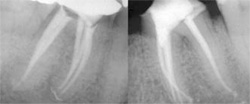 | |
| Figure 5 Fluorescein sodium was used in re-treating tooth No. 30. The chamber was moistened with the liquid and subjected to a curing light beam (left). The tissue tag was contained in a patent isthmus that was negotiated with a hand file (right). | Figure 6 The re-treatment from the previous figure showing three canals in the mesial root (left). The contralateral tooth also required treatment, also with a three-canal mesial root (right). | |
 |  | |
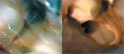
| Figure 7 Ground section of a crown with the radial array of the dentinal tubules (left). At the cemento-enamel junction (right), the same section demonstrates the perpendicular arrangement of the tubules relative to the canal space. | Figure 8 Radial dentin effect in an anterior crown access at the cemento-enamel junction. Note the dystrophic dentin at the center of the "sunburst" (left). Radial dentin in a molar access (right). The radial dentin points to the location of the MB2 canal. | |
 |  | |
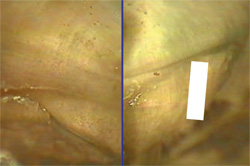
| Figure 9 Radiograph of tooth No. 14, with dystrophically obliterated canal spaces. The access reveals an iatrogenic post space, and the roof of the true chamber still intact (right). Note the mottled color and shading. | Figure 10 Higher power of the finished access (left). Note the homogenous color and "J" shape at the mesial floor (arrow). The MB2 canal will be located at that junction. The final radiograph is to the right. | |
 |  | |
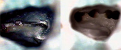
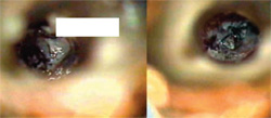
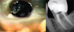
| Figure 11 A vertical fracture under an MO amalgam in tooth No. 14. Note the staining associated with the leakage of the restoration (left). After instrumentation, the fracture was seen to progress into the MB2 canal (right). | Figure 12 A suspected fracture (left) demonstrates the NaOCl bubbling effect along its course. A dead tract (right) appears similar, but fails to elicit the same reaction when NaOCl is added (arrow). | |
 |  | |
| Figure 13 A microreflection of the disto-palatal gingiva of tooth No. 13 reveals a small fracture stained with blood under the crown margin (arrow). | Figure 14 Furcation perforation of tooth No. 19, which was sealed by the operator with glass ionomer. Note the osseous defect in the furcation (left). The perforation was reopened and homeostasis was achieved (right). | |
 | 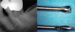 | |
| Figure 15 The perforation was sealed with MTA (gray formulation), and the site was covered with a permanent restoration (left). The 6-month recall radiograph reveals complete resolution of the furcation defect (right). | Figure 16 Preoperative radiograph of tooth No. 18, revealing a separated instrument in the MB canal (left). The staging instrument is fashioned from a Gates-Glidden bur by severing the tip with a diamond disc (right). This modified Gates-Glidden will create a platform around the coronal tip of the fragment. | |
 |  | |
| Figure 17 The platform has been created around the fragment end (left). The fragment end is just visible at the level of the dentin platform (arrow). By troughing circumferentially around the fragment, 2 mm to 3 mm of the file flutes have been uncovered (right). | Figure 18 Light ultrasonic vibrations dislodged the file and spun it coronally toward the chamber (left) and it was retrieved with a microsuction. The final radiograph of the treatment is seen at the right. | |
| About the Author | ||
 Stephen P. Niemczyk, DMD Stephen P. Niemczyk, DMD Director of Endodontic Microsurgery Harvard University Boston, Massachusetts Director of Endodontic Microsurgery Albert Einstein Medical Center Philadelphia, Pennsylvania Surgical Consultant National Naval Medical Center Bethesda, Maryland Private Practice Limited to Endodontics Drexel Hill, Pennsylvania | ||

